
Semi-submersible drilling platform casing pipe hole entering method

A drilling platform and semi-submersible technology, applied in the direction of drilling equipment and methods, underwater drilling, drilling equipment, etc., can solve the problems of casing running inclination, high requirements for drilling pressure control, unsuitable injection method, etc., to achieve Improved accuracy, reduced operating costs, and high versatility

Active Publication Date: 2021-09-21
CHINA NAT OFFSHORE OIL CORP +2
View PDF9 Cites 0 Cited by
  • Summary
  • Abstract
  • Description
  • Claims
  • Application Information

AI Technical Summary

Problems solved by technology

However, this method is not suitable for all sea areas. When using jetting to run the casing with high requirements on WOB control, when the seabed slope changes greatly, there are collapsed areas on the seabed, and complex terrain such as rough seabeds, the casing running process is prone to tilt and cause irregularities. suitable for spraying

Method used


Image

  • Semi-submersible drilling platform casing pipe hole entering method
  • Semi-submersible drilling platform casing pipe hole entering method
  • Semi-submersible drilling platform casing pipe hole entering method

Examples


Embodiment 1

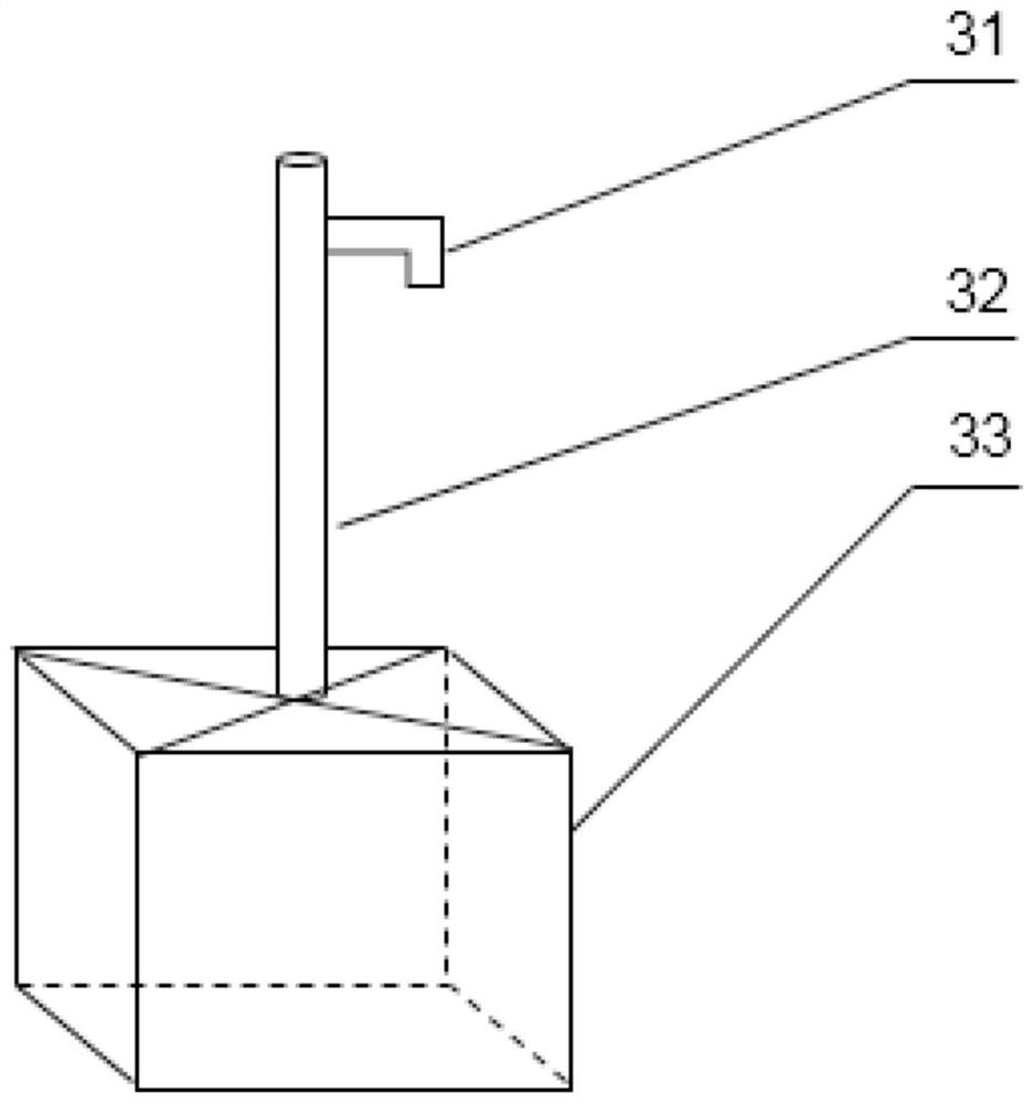
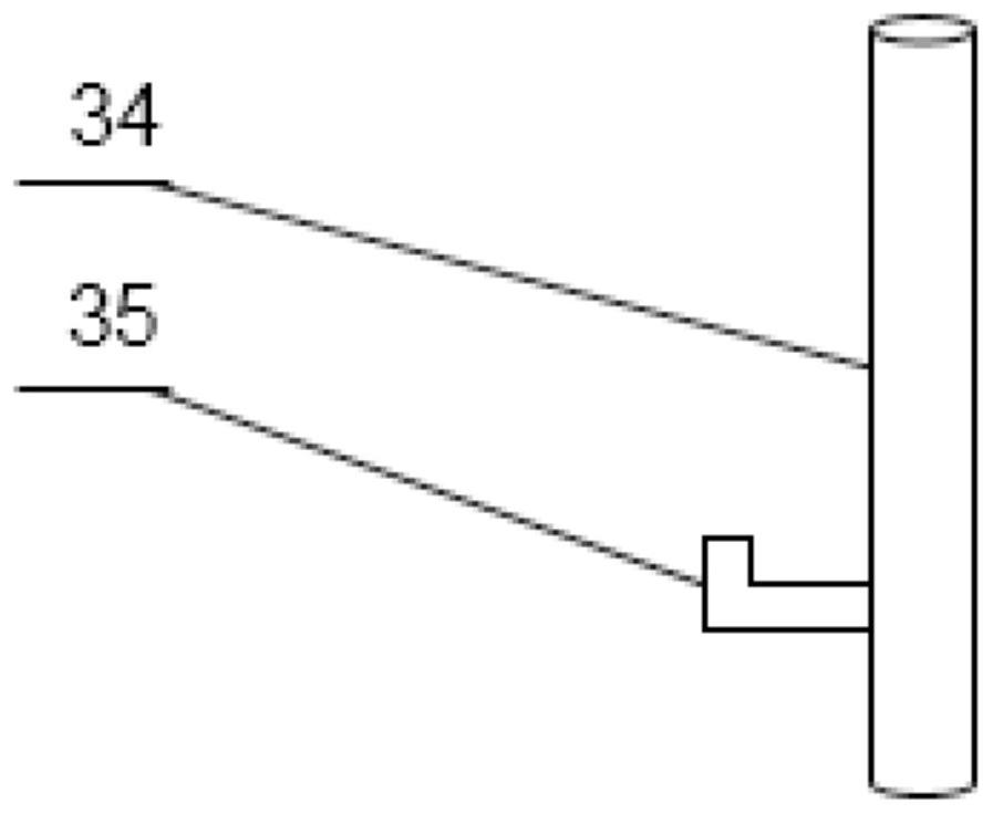
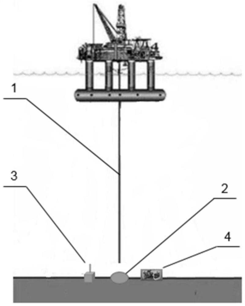
[0040] Such as figure 1 and figure 2 Shown, a kind of semi-submersible drilling platform casing drilling method comprises the following steps:

[0041] S10: Launch a beacon 3 at a distance of 5 meters from the target drilling position; the distance between the beacon 3 and the target drilling position is too small, and the position of the semi-submersible drilling platform affected by the waves will shift during the subsequent drilling process, As a result, the drill bit hits the beacon 3; when the distance between the beacon 3 and the target drilling position is too large, the detection accuracy will decrease. At the same time, the beacon 3 is fixed on the seabed mud to prevent the position of the beacon 3 being affected by the seabed current from shifting.

[0042] S20: The remote control ROV4 moves to a place 5 meters away from the target drilling position and stands by; the ROV4 is a remote operated unmanned submersible (Remote Operated Vehicle, ROV), which is a type of...

Embodiment 2

[0064] This embodiment is similar to Embodiment 1, the difference is that the step S10 in this embodiment: the beacon 3 is placed at a distance of 3 meters from the target drilling position; the step S20: the remote control ROV4 moves to a distance from the target drilling position Standby at 3 meters;

Embodiment 3

[0066] This embodiment is similar to Embodiment 1, the difference is that the step S10 in this embodiment: the beacon 3 is placed at a distance of 10 meters from the target drilling position; the step S20: the remote control ROV4 moves to a distance from the target drilling position Standby at 10 meters;


PUM


Abstract

A semi-submersible drilling platform casing pipe hole entering method comprises the following steps that S10, a beacon is tripped in the range 3-10 m away from a target drilling position; S20, an ROV is remotely controlled to move to the range 3-10 meters away from the target drilling position for standby; S30, a semi-submersible drilling platform conducts drilling operation at the target drilling position; S40, before a drilling tool is driven out of a drilled well, the ROV calibrates the relative positions of a borehole, the beacon and the ROV through sonar scanning; S50, when the semi-submersible drilling platform lowers a surface casing pipe to be close to a seabed mud line, the ROV scans the position of the surface casing pipe through sonar; and S60, by comparing the position, scanned by the ROV, of the surface casing pipe with the calibrated borehole position, an anchor chain of the semi-submersible drilling platform is adjusted so that the position of the surface casing pipe can coincide with the calibrated borehole position, and the surface casing pipe enters the borehole. The method is easy to operate, wide in application range and capable of improving the accuracy of casing pipe entering of the semi-submersible drilling platform during high-depth operation.

Description

technical field [0001] The invention relates to the technical field of offshore drilling, and more particularly, to a casing drilling method for a semi-submersible drilling platform. Background technique [0002] Use semi-submersible drilling platform to drill wells in deep ocean water areas. Since the guide plate is not lowered into the wellbore when drilling, it is often difficult to run into the surface casing after drilling when the drilling reaches the target well depth. The operating water depth of the semi-submersible drilling platform generally exceeds 100 meters, and the diameter of the wellbore does not exceed 1 meter. At a height of 100 meters, the surface casing is smoothly sent into the wellbore with a diameter of less than 1 meter, and it is still impossible Seeing the wellbore directly, it is very difficult to enter the surface casing. Although the current semi-submersible drilling platform is equipped with an underwater robot (ROV) for sonar scanning to assi...

Claims


Application Information

Patent Timeline
Patent Type & Authority Applications(China)
IPC IPC(8): E21B7/20E21B7/12E21B41/00
CPCE21B7/20E21B7/12E21B41/0014
Inventor 黄熠李炎军罗鸣张万栋韩成肖平娄益伟杨玉豪张超
Owner CHINA NAT OFFSHORE OIL CORP
Learn More