Outdoor three-phase transformer with passive protection mechanism

A technology of three-phase transformers and protection mechanisms, applied in the field of transformers, can solve the problems of being unable to pass through weather factors, prone to aging, and affecting service life, so as to reduce maintenance and replacement costs, reduce maintenance personnel expenses, and reduce maintenance costs.

Active Publication Date: 2021-09-21
徐州强森电气有限公司
View PDF5 Cites 0 Cited by
  • Summary
  • Abstract
  • Description
  • Claims
  • Application Information

AI Technical Summary

Problems solved by technology

[0005] In order to solve the above technical problems, the present invention provides an outdoor three-phase transformer with a passive protection mechanism to solve the problem that when the existing three-phase transformer is used outdoors, it lacks protective devices, and after a long time of use, it is prone to aging, resulting in It cannot cope with bad weather, which will affect the service life, and when the existing three-phase transformer is used outdoors, when it encounters a storm or hail, it cannot automatically trigger the protection mechanism for protection, and cannot passively trigger the protection mechanism through weather factors.

Method used


Image

  • Outdoor three-phase transformer with passive protection mechanism
  • Outdoor three-phase transformer with passive protection mechanism
  • Outdoor three-phase transformer with passive protection mechanism

Examples


Embodiment 1

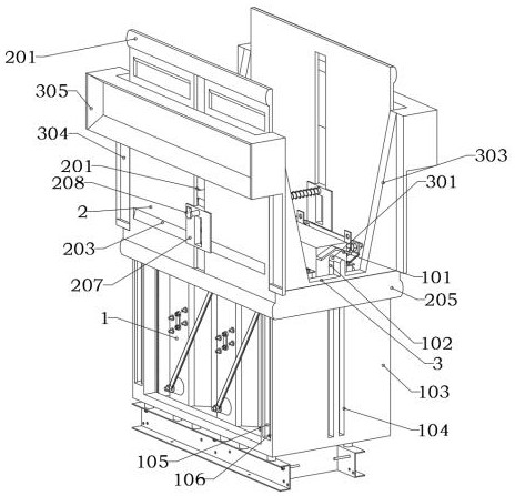
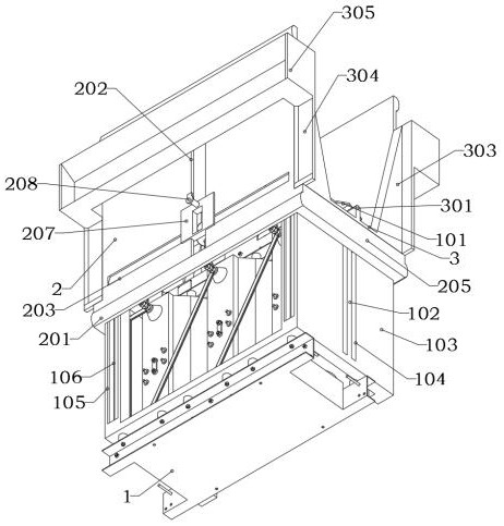
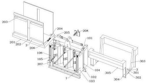
[0030] as attached figure 1 To attach Figure 10 Shown:

[0031]The invention provides an outdoor three-phase transformer with a passive protection mechanism, which includes a main body 1; the main body 1 is a three-phase transformer body, and a protective part 2 is installed on both sides of the top of the main body 1; the protective part 2, the protective part 2 includes a guide Flow heat dissipation mechanism, the outer side of the protective part 2 is equipped with a diversion heat dissipation mechanism, the protective part 2 plays the role of protection installed on both sides of the main body 1, the protective part 2 is a rectangular plate structure, and the protective part 2 is made of hard anti-aging plastic material , two triggers 3 are installed on both sides of the guard 2; the trigger 3, the trigger 3 is a rectangular plate-shaped structure, the trigger 3 is installed on the top of the connector 205, and the trigger 3 plays a role in passing the force with the top...

Embodiment 2

[0042] When the protection does not need to be passively triggered, so that the main body 1 can be protected all the time, before the installation of the main body 1, the displacement of the trigger 3 can be pushed by manpower, so that the limit rod 301 can be separated from the top of the push rod 102, so that the protection Part 2 automatically moves downward after releasing the limit, so that the protective part 2 can continue to protect on both sides of the main body 1, and then pull the contact rod 208 to move, so that the spring can be compressed, and then control the moving part 207 to move downward, and then loosen Open the contact rod 208, so that the contact rod 208 can contact the bottom of the main body 1, and the chicken assists in fixing the guard 2, so that the guard 2 can be on the outside of the main body 1 for protection.

Embodiment 3

[0044] The top plate 305 and the outer ends of the support rods 303 can be replaced with plastic materials, so that the top plate 305 will only be triggered when encountering a large storm and hail, and then the protective member 2 will be triggered and used in relatively bad weather.

[0045] When in use: when the device needs to be used, the protective part 2 can be controlled by manpower to move upward, so that the force plate 204 can move upward inside the guide groove 105, and then the spring on the outside of the guide rod 106 is compressed, and at the same time the trigger part 3 and move together, so that the inner side of the top of the limit rod 301 can be in contact with the guide plate 101, and then be guided to move, and at the same time push the spring inside the groove 206 to push the contact plate 302 to reset, so that the upper inner end of the limit rod 301 can be automatically in position. The top of the ejector rod 102, and then the protective part 2 and the...


PUM


Abstract

The invention provides an outdoor three-phase transformer with a passive protection mechanism, which relates to the field of transformers, and aims to solve the problems that when an existing three-phase transformer is used outdoors and encounters rainstorm or hail, a protection mechanism cannot be automatically triggered for protection, and the protection mechanism cannot be passively triggered through weather factors. Theoutdoor three-phase transformer with a passive protection mechanism comprises a main body; the main body is a three-phase transformer body, and protective pieces are mounted on the two sides of the top end of the main body; the protective piece comprises a flow guide heat dissipation mechanism, the flow guide heat dissipation mechanism is arranged on the outer side of the protective piece, the protective piece is of a rectangular plate-shaped structure, and the protective piece is made of hard anti-aging plastic materials. When a rainstorm or hail occurs, the outer end of the top plate or the supporting rod made of the foam material is stressed to generate displacement, so that the trigger plate can move forwards or backwards in order, the limiting rod can be separated from the interior of the top end of the top rod, the trigger piece and the protective piece can be released from limiting, and the protective piece can automatically move downwards to be located on the two sides of the main body for protection.

Description

technical field [0001] The invention belongs to the technical field of transformers, and more specifically relates to an outdoor three-phase transformer with a passive protection mechanism. Background technique [0002] Transformer is a device that uses the principle of electromagnetic induction to change AC voltage. The main components are primary coil, secondary coil and iron core (magnetic core). The main functions are: voltage conversion, current conversion, impedance conversion, isolation, voltage stabilization (magnetic Saturated transformer), etc., when the transformer is used outdoors, it is usually affected by external factors, which leads to a shortened service life of the transformer. [0003] For example, the application number: CN201910762728.0 relates to a transformer protection device, including an iron yoke formed by the iron core protruding from the coil, the first protection structure is used to be arranged on the iron yoke, the first protection structure a...

Claims


Application Information

Patent Timeline
Patent Type & Authority Applications(China)
IPC IPC(8): H01F27/02H01F27/23H01F27/16H01F27/08
CPCH01F27/025H01F27/23H01F27/16H01F27/085
Inventor 路新奎
Owner 徐州强森电气有限公司
Why Eureka
Try Eureka