Drilling equipment for machining
A drilling equipment and mechanical processing technology, which is applied in the direction of metal processing equipment, drilling/drilling equipment, boring/drilling, etc., can solve the problems that affect the normal processing of metal workpieces, cannot mechanically process waste, and the sliding of the worktable is blocked and other problems, to achieve the effect of prolonging the service life, avoiding unstable support, and avoiding the adhesion of waste debris
- Summary
- Abstract
- Description
- Claims
- Application Information
AI Technical Summary
Problems solved by technology
Method used
Image

Examples
Embodiment 1
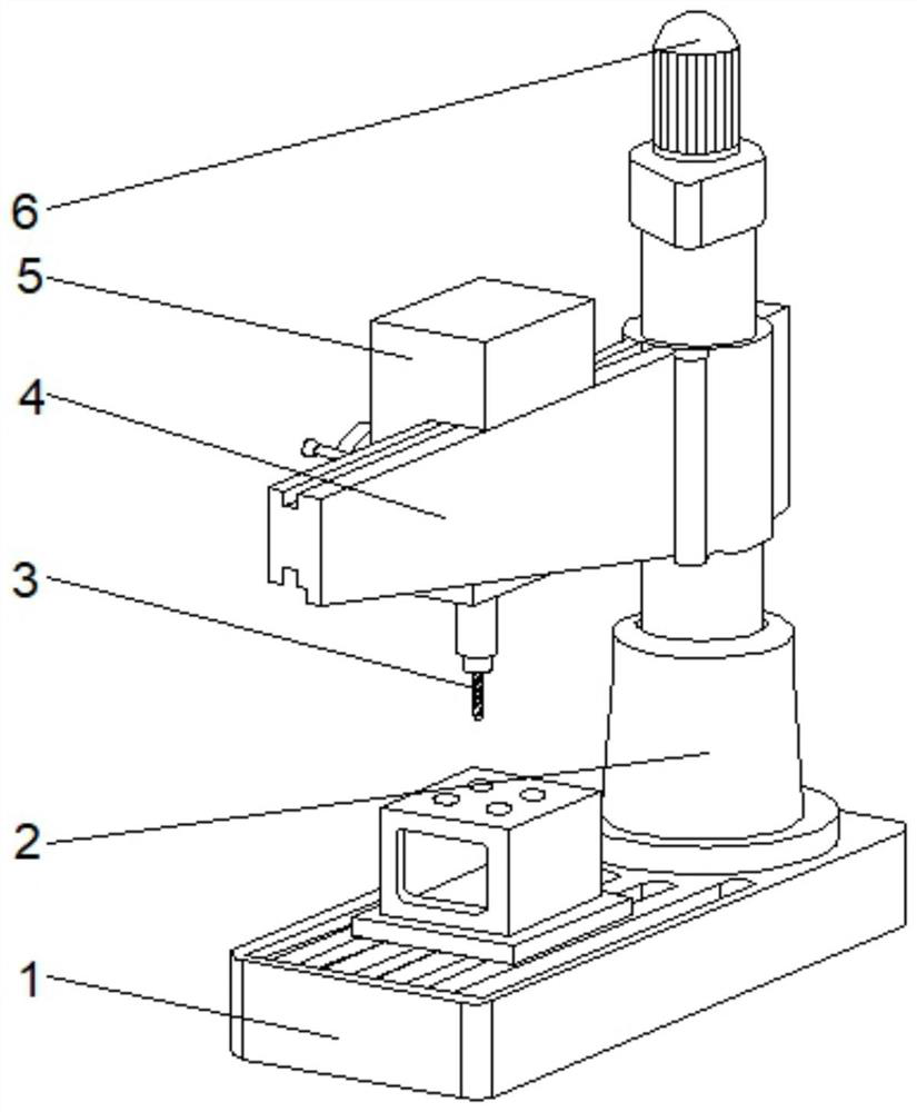
[0035] see Figure 1-2 , the present invention provides a technical solution: a kind of drilling equipment for mechanical processing, including a column 2, the bottom end of the column 2 is fixedly connected with a cleaning device 1, the middle part of the top of the column 2 is provided with a motor 6, and the output shaft of the motor 6 runs through the The column 2 extends to the inside of the column 2, the outer surface of the middle part of the column 2 is provided with a mobile frame 4, the middle position of the back top of the mobile frame 4 is provided with a fixer 5, and the bottom of the fixer 5 is fixedly connected with a drill bit 3.
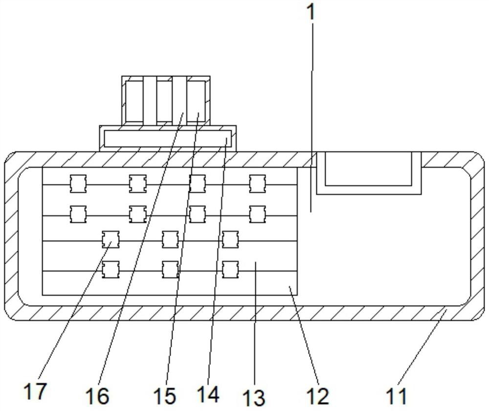
[0036]Wherein, cleaning device 1 comprises base 11, and the top right side of base 11 is fixedly connected with workbench 14, and the top of workbench 14 is fixedly connected with clamping block 15, and both sides of the top of clamping block 15 are provided with through hole 16, The bottom of the through hole 16 runs through the cl...
Embodiment 2
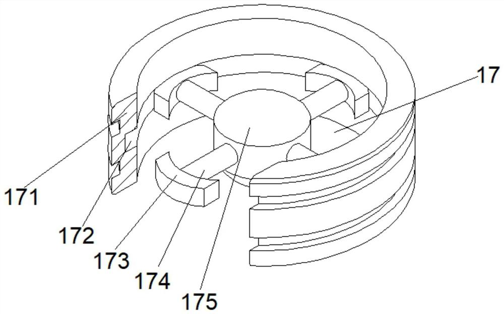
[0039] see Figure 1-4 On the basis of Embodiment 1, the present invention provides a technical solution: the cleaning mechanism 17 includes a housing 171, a chute 172 is provided in the middle of the inner wall of the housing 171, and auxiliary mechanisms 173 are provided on the inner walls of both sides of the chute 172 to assist The middle part of the mechanism 173 away from the housing 171 is fixedly connected with a fixed column 174 , and the end of the fixed column 174 away from the auxiliary mechanism 173 is fixedly connected with a rotating shaft 175 .
[0040] Among them, the auxiliary mechanism 173 includes an auxiliary frame d1, and the middle position of the top of the inner cavity of the auxiliary frame d1 is fixedly connected with an overhanging mechanism d6, and the two sides of the bottom of the overhanging mechanism d6 are fixedly connected with supporting rods d5, and the two sides of the supporting rod d5 An auxiliary block d4 is arranged on the top of the o...
Embodiment 3
[0043] see Figure 1-7 , on the basis of Embodiment 1 and Embodiment 2, the present invention provides a technical solution: the outreach mechanism d6 includes a pusher frame d61, and the top of the inner cavity of the pusher frame d61 is fixedly connected with a joint plate d62, and the joint plate d62 The middle parts of the inner walls on both sides are fixedly connected with the push rod d64, and the two sides of the bottom of the outer pushing frame d61 are fixedly connected with the elastic sheet d65, and the position of the elastic sheet d65 away from the outer pushing frame d61 is fixedly connected with the clamping plate d63.
[0044] Wherein, the clamping plate d63 includes a plate body t1, a top block t3 is arranged on the top of the plate body t1, and a force receiving plate t2 is fixedly connected to the bottom of the plate body t1.
[0045] Wherein, the force bearing plate t2 includes a bearing plate t22, the top of the inner cavity of the bearing plate t22 is fi...
PUM
 Abstract
Description
Claims
Application Information
 - R&D
- Intellectual Property
- Life Sciences
- Materials
- Tech Scout
- Unparalleled Data Quality
- Higher Quality Content
- 60% Fewer Hallucinations
Browse by: Latest US Patents, China's latest patents, Technical Efficacy Thesaurus, Application Domain, Technology Topic, Popular Technical Reports.
© 2025 PatSnap. All rights reserved.Legal|Privacy policy|Modern Slavery Act Transparency Statement|Sitemap|About US| Contact US: help@patsnap.com