A high resistivity resistance alloy wire melting device
An alloy wire and high-resistance technology, which is applied in the field of high-resistivity resistance alloy wire melting devices, can solve problems such as difficult equipment cleaning and increased production costs, and achieve the effects of ensuring processing quality, saving production costs, and avoiding environmental pollution
- Summary
- Abstract
- Description
- Claims
- Application Information
AI Technical Summary
Problems solved by technology
Method used
Image

Examples
Embodiment 1
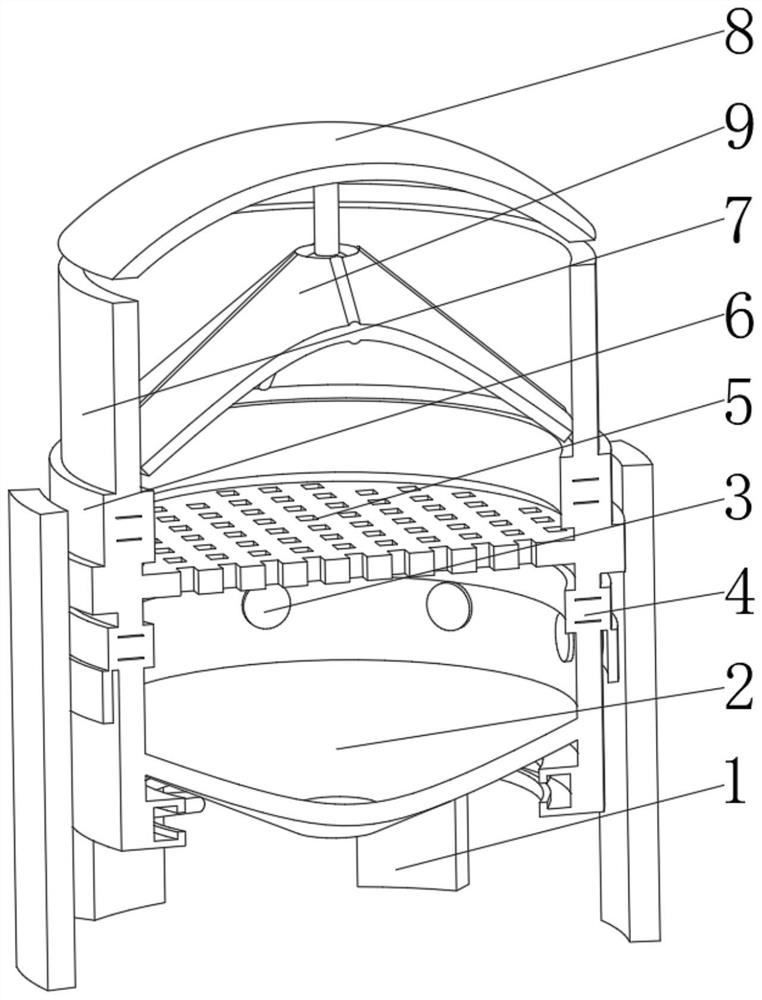
[0037] See figure 1 , 24, the present invention provides a technical solution: a high resistance coefficient of electrical resistance coefficient, specifically:
[0038] Support frame 1, the support frame 1 has an arc plate body, and a collection device 2 mounted on the inner surface of the arc gauge, and is mounted on the top of the collecting device 2, a ring flake furnace 3, and a lower assembly mounted at the top of the annular flake furnace 3 Device 4, and mounted the smelting device 5 on top of the lower assembly device 4, and an upper assembly device 6 mounted on top of the smelting device 5, and is mounted on the top of the upper assembly device 6, and mounted on top of the injection cartridge 7 The active end cover 8 is attached to the intermediate position of the movable end cover 8, which is convenient to disassemble and clean each component through the overall segmentation design, avoiding the melting material in the device during the melting process. Solidification, r...
Embodiment 2
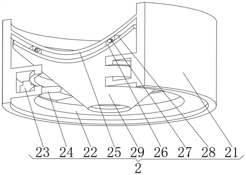
[0048] See Figure 1-4 Based on the example one, the present invention provides a technical solution: collecting device 2 includes:
[0049] The protective barrel 21 has an annular body, and a concave rail 22 mounted on the bottom of the annular body, and the moving motor 23 mounted inside the concave rail 22, and a friction mounted on the side of the moving motor 23 away from the annular main body. Rod 24;
[0050] The collecting plate 25 has a cone body, and a lower recessed rail 26 mounted at the bottom of the current collector plate 25, and the ball beads 27 on top of the lower curver 26, and mounted on top of the beads 27 The upper recess rail 28 is mounted on the friction plate 29 at the bottom of the upper recealed rail 28. The friction plate 29 is rubbed by the rib 24 by the friction bar 24, so that the current collecting plate 25 is interrogated with the friction plate 29 to distract, and the material collected after the smelt is shaken, and it is avoided. 25 surface stays...
Embodiment 3
[0054] See Figure 1-5 Based on the first and embodiment 2, the present invention provides a technical solution: the auxiliary feed device 9 includes:
[0055] The mounting rod 91 has a columnar body, and a ball head member 92 mounted on the bottom of the columnar body, and is mounted on the strip 93 outer surface of the ball member 92, and an elastic plate 94 mounted on the outer surface of the strip 93 And the vacuum cavity 95 in the middle of the elastic plate 94 is opened. The vacuum cavity 95 of the elastic plate 94 is designed to make the overall assembly can buffer the feed of the feed, and achieve self-protection of the components, and the umbrella strip 93 and the assembly of the elastic plate 94 are concentrated in the exhaust gas. It is easy to concentrate on collecting and purifying.
[0056] When used, when the melting material is dropped, the elastic plate 94 carries the smelting material and guides, the weight of the smelting material material causes the strut 93 to ...
PUM
 Abstract
Description
Claims
Application Information
 - R&D
- Intellectual Property
- Life Sciences
- Materials
- Tech Scout
- Unparalleled Data Quality
- Higher Quality Content
- 60% Fewer Hallucinations
Browse by: Latest US Patents, China's latest patents, Technical Efficacy Thesaurus, Application Domain, Technology Topic, Popular Technical Reports.
© 2025 PatSnap. All rights reserved.Legal|Privacy policy|Modern Slavery Act Transparency Statement|Sitemap|About US| Contact US: help@patsnap.com