Fuel cell humidification system

A humidification system, fuel cell technology, applied in fuel cells, circuits, electrical components, etc., can solve the problem of reducing the volume power density and mass power density of the system, increasing the bypass passage or adjusting the temperature before and after the humidifier, increasing the complexity of the system and Control difficulty and other issues to achieve the effects of controllable humidification capacity, compact structure and small footprint

Pending Publication Date: 2021-09-24
BEIJING SINOHYTEC
View PDF0 Cites 0 Cited by
  • Summary
  • Abstract
  • Description
  • Claims
  • Application Information

AI Technical Summary

Problems solved by technology

[0005] The present invention provides a fuel cell humidification system to solve the problem that the volume and weight of existing humidifiers proposed in the background technology are relatively large, and the volume po

Method used


Image

  • Fuel cell humidification system
  • Fuel cell humidification system
  • Fuel cell humidification system

Examples


Embodiment

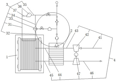
[0032] Examples, see Figure 1-2 , a fuel cell humidification system, comprising an electric stack 1 and an air-to-air cooler 2, the electric stack 1 is connected to a circulating hydrogen intake assembly 3 by pipes;

[0033] Both sides of the air-to-air cooler 2 are detachably connected to the mobile air transmission assembly 4, and the middle part of the mobile air transmission assembly 4 is detachably connected to the electric stack 1;

[0034] A circulating water assembly 5 is provided between the air-to-air cooler 2 and the electric stack 1 , and one end of the circulating water assembly 5 is detachably connected to the circulating hydrogen intake assembly 3 .

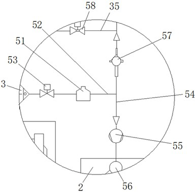
[0035] see figure 1 , the circulating hydrogen intake assembly 3 includes a first intake pipe 31, the first intake pipe 31 is detachably connected to the electric stack 1, one side of the electric stack 1 is detachably connected to a first connecting pipe 32, the first A connecting pipe 32 is a detachable water ...

Embodiment 2

[0039] Embodiment 2, a fuel cell humidification system, including the following control steps:

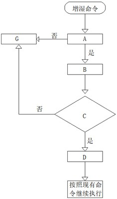
[0040] Step S1: Humidification command;

[0041]Step A: Detect or calculate the target current point humidity A1, if the humidity is less than the target value SETA, output to B when yes, and output to G when no;

[0042] Step B: Calculate the water pump speed b according to the humidification amount A1, and then go to C after obtaining the value;

[0043] Step C: Execute the speed of the water pump calculated in step B to perform humidification;

[0044] Step D: Real-time detection or calculation of the target current point humidity A2, whether the humidity is less than the target value SETA;

[0045] Step E: When the humidity obtained in step D is less than the target value SETA, output to E, calculate the pump speed b2 according to the humidification amount A3, and finally continue to execute according to the existing command;

[0046] Step G: When the values ​​calculated in ...


PUM


Abstract

The invention provides a fuel cell humidification system which comprises an electric pile and an air-air intercooler, and the electric pile is connected with a circulating hydrogen inlet assembly through a pipeline; the two sides of the air-air intercooler are detachably connected with a flowing type air transmission assembly, and the middle part of the flowing type air transmission assembly is detachably connected with the electric pile; a circulating water assembly is arranged between the air-air intercooler and the electric pile, and one end of the circulating water assembly is detachably connected with the circulating hydrogen inlet assembly. According to the invention, the structure is more compact through connection of the circulating water assembly and the air-air intercooler, and meanwhile, water and hydrogen are recycled, so that more energy is saved.

Description

technical field [0001] The invention relates to the technical field of fuel cell humidification, and mainly relates to a fuel cell humidification system. Background technique [0002] A fuel cell is a chemical device that directly converts the chemical energy of fuel into electrical energy, also known as an electrochemical generator. It is the fourth power generation technology after hydropower, thermal power and atomic power. Because fuel cells are The Gibbs free energy in the chemical energy of the fuel is partially converted into electrical energy through an electrochemical reaction, which is not limited by the Carnot cycle effect, so the efficiency is high; in addition, the fuel cell uses fuel and oxygen as raw materials; at the same time, there are no mechanical transmission parts , so there is no noise pollution, and very little harmful gas is emitted. It can be seen that from the perspective of energy saving and ecological environment protection, fuel cells are the mo...

Claims


Application Information

Patent Timeline
IPC IPC(8): H01M8/04119H01M8/04089
CPCH01M8/04141H01M8/04097Y02E60/50
Inventor 胥巍巍徐云飞邓景聪曲观书李飞强
Owner BEIJING SINOHYTEC
Why Eureka
Try Eureka