
Compression device used for garbage treatment and provided with light separating structure, and use method of compression device

A technology of waste treatment and separation structure, which is applied in the direction of separating solids from solids with airflow, solid separation, grain treatment, etc. It can solve the problems of not having light separation structure, unable to classify solid waste and light waste, etc. , to achieve the effect of facilitating classification processing, improving processing effect and processing efficiency, and ensuring accuracy

Pending Publication Date: 2021-09-28
深圳市保洁恒环境产业有限公司
View PDF6 Cites 2 Cited by
  • Summary
  • Abstract
  • Description
  • Claims
  • Application Information

AI Technical Summary

Problems solved by technology

[0004] The object of the present invention is to provide a compacting device with a lightweight separation structure for garbage disposal and a method of use thereof, so as to solve the problem that the compression device for garbage disposal proposed in the above-mentioned background technology does not have a lightweight separation structure and cannot separate solid waste from light waste. The problem of classification

Method used


Image

  • Compression device used for garbage treatment and provided with light separating structure, and use method of compression device
  • Compression device used for garbage treatment and provided with light separating structure, and use method of compression device
  • Compression device used for garbage treatment and provided with light separating structure, and use method of compression device

Examples


Embodiment Construction

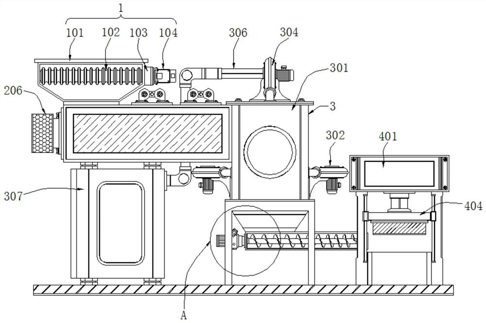
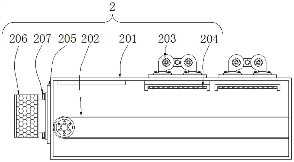
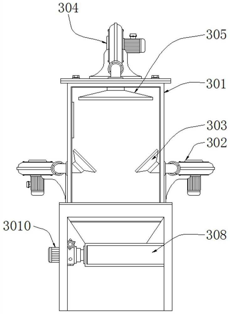
[0035] see Figure 1-5, a compression device with a lightweight separation structure for garbage disposal and its use method, comprising a crushing assembly 1 and a compression assembly 4, a drying assembly 2 is connected to the lower end of the crushing assembly 1, and a separation assembly is connected to the right side of the drying assembly 2 3. The separation assembly 3 includes a separation bin 301, a blower 302, an air outlet 303, a blower fan 304, a suction port 305, a conduit 306, a collection bin 307, a conveying pipeline 308, an auger 309 and a driving motor 3010, and the outer two sides of the separation bin 301 are The middle part of the side is provided with a blower 302, and one end of the blower 302 is connected with an air outlet 303, and the middle part of the upper end of the separation chamber 301 is provided with a blower 304, and the lower end of the blower 304 is connected with a suction port 305, and the left side of the blower 304 is connected with a co...


PUM


Abstract

The invention discloses a compression device used for garbage treatment and provided with a light separating structure, and a use method of the compression device, and relates to the technical field of garbage treatment. The compression device used for garbage treatment and provided with the light separating structure comprises a crushing assembly and a compression assembly, wherein the lower end of the crushing assembly is connected with a drying assembly, and the right side of the drying assembly is connected with a separating assembly; and the separating assembly comprises a separating bin, air blowers, air outlet ports, a fan, a suction port, a guide pipe, a collecting bin, a conveying pipeline, an auger and a driving motor. According to the invention, the air blowers arranged at the two sides of the outer portion of the separating bin are matched with the air outlet ports formed in the two sides of the inner portion of the separating bin, dried garbage conveyed into the separating bin through a conveying belt (202) can be subjected to separating treatment work for solid garbage and light garbage, the solid garbage falls into the bottom of the separating bin due to the gravity of the solid garbage, and the light garbage is sucked into the collecting bin under the driving of the fan due to the matching of upward airflow in the separating bin and the suction port formed in the top of the separating bin, so that the effect of light separating is realized.

Description

technical field [0001] The invention relates to the technical field of garbage treatment, in particular to a compression device with a lightweight separation structure for garbage treatment and a method for using the same. Background technique [0002] Garbage is solid waste generated in human daily life and production. Due to the large amount of discharge, complex and diverse components, and polluting, resourceful and social nature, it needs harmless, resourceful, reduction and socialized treatment. If not handled properly, it will pollute the environment, affect environmental sanitation, waste resources, destroy production and living safety, and disrupt social harmony. Garbage disposal is to quickly remove garbage, and conduct harmless treatment, and finally make reasonable use of it. Compressors are used during waste disposal. [0003] The compression devices for waste treatment on the market do not have a light-weight separation structure, and have the disadvantage of ...

Claims


Application Information

Patent Timeline
Patent Type & Authority Applications(China)
IPC IPC(8): B09B3/00B09B5/00B02C21/00B07B7/01A61L2/06B30B1/32
CPCB09B3/00B09B5/00B02C21/00B07B7/01A61L2/06B30B1/32
Inventor 胡容文
Owner 深圳市保洁恒环境产业有限公司
Learn More