Laser electric welding device capable of being adjusted in all directions

An all-round, laser technology, applied in the direction of laser welding equipment, welding equipment, metal processing equipment, etc., can solve the problems such as the inability to adjust the laser welding head, and achieve the effect of precise welding and increased accuracy

Active Publication Date: 2021-09-28
IANGSU COLLEGE OF ENG & TECH
View PDF7 Cites 2 Cited by
  • Summary
  • Abstract
  • Description
  • Claims
  • Application Information

AI Technical Summary

Problems solved by technology

[0003] For example, the Chinese patent whose publication number is CN211219161U proposes a multi-station laser welding equipment for auto parts. The hand wheel drives the rotating shaft to rotate, and the rotating shaft rotates the support runner through the connection key, and the support runner drives the welded auto parts to rotate, so as to realize the work in the circumferential direction of the auto parts, enhance the uniformity of welding, and improve the welding accuracy. Quality, by turning the adjustment wheel, the adjustment wheel drives the adjustment shaft to rotate, and the rotation of the adjustment shaft drives the clamping tool to rotate, so that the angle of the plane of the clamped auto parts can be changed, but the laser welding device cannot achieve this during welding. The all-round adjustment of the laser welding head can only weld one side of the parts. In order to solve the above problems, we propose a laser welding device that can be adjusted in all directions

Method used


Image

  • Laser electric welding device capable of being adjusted in all directions
  • Laser electric welding device capable of being adjusted in all directions
  • Laser electric welding device capable of being adjusted in all directions

Examples


Embodiment Construction

[0043] The following will clearly and completely describe the technical solutions in the embodiments of the present invention with reference to the accompanying drawings in the embodiments of the present invention. Obviously, the described embodiments are only some, not all, embodiments of the present invention. Based on the embodiments of the present invention, all other embodiments obtained by persons of ordinary skill in the art without making creative efforts belong to the protection scope of the present invention.

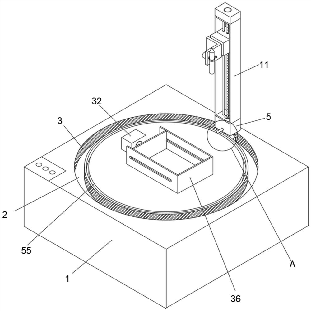
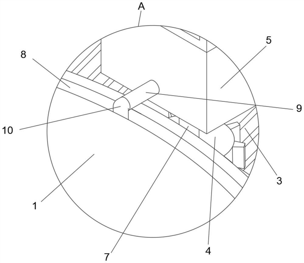
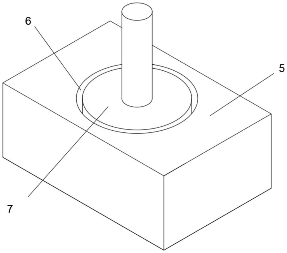
[0044] refer to figure 1 , figure 2 , image 3 , Figure 4 , Figure 5 , Image 6 and Figure 7 , a laser welding device that can be adjusted in all directions, including a welding station 1, a PLC controller is embedded in the top surface of the welding station 1, by setting the PLC controller, the effect of controlling the operation and stop of the laser welding device can be realized, and the welding The top surface of the table 1 is provided with a ...


PUM


Abstract

The invention discloses a laser electric welding device capable of being adjusted in all directions. According to the technical scheme, the laser electric welding device capable of being adjusted in all directions is characterized by comprising a welding table, a first instrument box and a limiting groove, wherein a PLC is embedded in the top face of the welding table; a moving groove is formed in the top face of the welding table, a plurality of tooth grooves are formed in the two sides of the interior of the moving groove, a gear is arranged inside the moving groove, and the gear is meshed with the tooth grooves; the first instrument box is arranged on the top face of the welding table, a rotating groove is formed in the bottom face of the first instrument box, and a first stepping motor is fixedly connected into the rotating groove in a sleeved mode; and the limiting groove is formed in the top face of the welding table, a supporting column is fixedly arranged on one side of the first instrument box, and a universal ball is fixedly arranged on one side of the supporting column. The first instrument box is driven to rotate around the rotating groove through rotation of the gear inside the rotating groove, and therefore, the effect of welding a weldment material on the top face of the welding table in all directions is achieved.

Description

technical field [0001] The invention relates to the technical field of laser electric welding, in particular to a fully adjustable laser electric welding device. Background technique [0002] Laser welding is an efficient and precise welding method that uses a high-energy-density laser beam as a heat source. Laser welding is one of the important aspects of the application of laser material processing technology. It is mainly used for welding thin-walled materials and low-speed welding. The welding process is of heat conduction type, that is, the laser radiation heats the surface of the workpiece, and the surface heat diffuses to the interior through heat conduction. By controlling the laser pulse Parameters such as width, energy, peak power and repetition frequency make the workpiece melt and form a specific molten pool. Due to its unique advantages, it has been successfully applied in the precision welding of micro and small parts. [0003] For example, the Chinese patent ...

Claims


Application Information

Patent Timeline
Patent Type & Authority Applications(China)
IPC IPC(8): B23K26/21B23K26/70
CPCB23K26/21B23K26/70B23K26/702Y02P70/10
Inventor 陈益飞巫邵波
Owner IANGSU COLLEGE OF ENG & TECH
Why Eureka
Try Eureka