
Water surface floating garbage cleaning equipment

A technology for garbage cleaning and water surface floating, which is applied in the direction of open water surface cleaning, passenger handling equipment, cargo handling equipment, etc. Improve performance, clean up quickly and easily

Inactive Publication Date: 2021-09-28
刘晨皓
View PDF0 Cites 2 Cited by
  • Summary
  • Abstract
  • Description
  • Claims
  • Application Information

AI Technical Summary

Problems solved by technology

[0005] Aiming at the deficiencies of the prior art, the present invention provides a kind of equipment for cleaning floating garbage on the water surface, which solves the problem of relying on manual labor when cleaning the floating garbage on the water surface, which is time-consuming and laborious, and has low work efficiency. Some use machinery for salvage cleaning, but the adaptability is poor. , for flexible flake debris such as leaves and plastic bags floating in the water, a water film will form with the moisture attached to the surface, sticking to the equipment, making it difficult to dump the debris, causing the debris to form accumulations, affecting the collection of floating garbage cleanup, reduced usage performance

Method used


Image

  • Water surface floating garbage cleaning equipment
  • Water surface floating garbage cleaning equipment
  • Water surface floating garbage cleaning equipment

Examples


Embodiment example 1

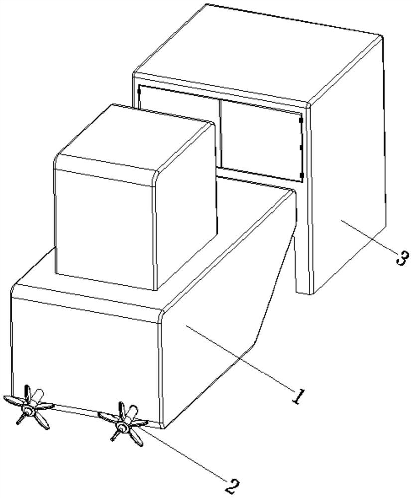
[0032] see Figure 1-7 , the present invention provides a technical solution: a device for cleaning floating garbage on the water surface, including a hull 1, a propeller 2, and a garbage cleaning device 3. The device 3 is arranged on the end of the hull 1 away from the propeller 2;

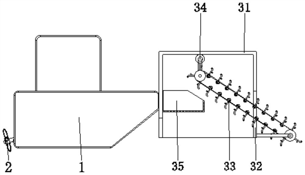
[0033] Garbage salvage device Garbage cleaning device 3 is provided with shell 31, breach 32, rubbish salvage device 33, power mechanism 34, storage barrel 35, and the surface side of rubbish salvage device shell 31 is fixedly connected with the end of hull 1, and the garbage salvage device breach 32 is provided on both sides corresponding to the bottom of the surface of the shell 31. The garbage salvage device 33 is arranged in the inside of the shell 31 and is positioned at the position of the gap 32. One end of the device 33 is mated and connected, and one side of the surface of the storage barrel 35 of the garbage salvage device is fixedly connected to one side of the inner wall of the housi...

Embodiment example 2

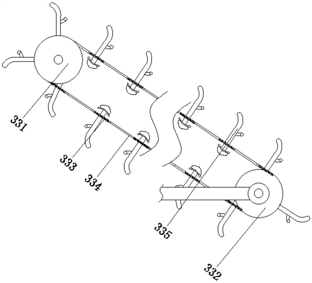
[0035]The garbage salvage device 33 is provided with a driving roller device 331, a driven roller 332, a conveyor belt 333, a slot 334, and a gear shifting device 335. The garbage salvaging device driving roller device 331 is rotatably connected between the two sides corresponding to the inner wall of the housing 31, The garbage salvage device driven roller 332 is rotatably connected to the surface bottom of the casing 31 and is close to the position of the gap 32, the garbage salvage device conveyor belt 333 is arranged on the surface of the driving roller device 331 and the driven roller 332, and the garbage salvage device slot 334 is provided in the On the surface of the conveyor belt 333, the gear shifting device 335 of the garbage salvage device is fixed on the surface of the conveyor belt 333 and close to the position of the slot 334, and the driving roller device 331 is driven by the power mechanism 34, so that the conveyor belt 333 drives the gear shifting device 335 to ...

Embodiment example 3

[0037] The driving roller device 331 is provided with a roller body 3311, a groove 3312, and a pressing device 3313. The end of the garbage salvage device roller body 3311 is rotationally connected with the inner wall of the housing 31, and the garbage salvage device groove 3312 is provided on the surface of the roller body 3311. The rubbish salvage device pressing device 3313 is arranged inside the roller body 3311 and is located at the position of the groove 3312. When the driving roller device 331 is driven by the conveyor belt 333 to move continuously, it can timely salvage the floating garbage on the water surface, and at the same time the driving roller device When 331 moves to the position of the driving roller device 331, the end of the driving roller device 331 is in the groove 3312, and presses the pressing device 3313 to promote the dumping of the salvaged garbage and reduce the situation of sticking due to the water film .

[0038] The pressing device 3313 is provi...


PUM


Abstract

The invention discloses water surface floating garbage cleaning equipment which comprises a ship body, a propeller and a garbage cleaning device, the propeller is arranged at one end of the ship body and close to the bottom, the garbage cleaning device is arranged at the end, away from the propeller, of the ship body, and one side of the surface of a shell is fixedly connected with the end of the ship body. The notches are formed in the two corresponding sides of the bottom of the surface of the shell, a garbage salvaging device is arranged in the shell and located at the notches, and a power mechanism is arranged on the top of the inner wall of the shell and connected with one end of the garbage salvaging device in a matched mode. One side of the surface of a storage barrel is fixedly connected with one side of the inner wall of the shell, and the storage barrel is located at the end of the garbage salvaging device. The invention relates to the technical field of environmental protection equipment of water conservancy projects. According to the water surface floating garbage cleaning equipment, the purpose of rapid cleaning is achieved, manual cleaning is not needed, the manual labor amount is reduced, time and labor are saved, the influence of water film adhesion is reduced, garbage cleaning is rapid and convenient, and the use performance is improved.

Description

technical field [0001] The invention relates to the technical field of water conservancy engineering environmental protection equipment, in particular to equipment for cleaning floating garbage on the water surface. Background technique [0002] As the water surface flows, it accumulates near the shore and in the corners of the water surface, becoming "floating garbage" on the water. Floating garbage on the water surface can be divided into tangible garbage and invisible garbage, large garbage and small garbage, hard garbage and soft garbage, organic garbage and inorganic garbage, etc. If these rubbish are not removed, it will aggravate water pollution and affect the senses. After the completion of the water conservancy dam project, in order to conveniently control the water flow of the dam, it is necessary to set up drainage facilities on the dam, but there will inevitably be various floating objects on the river surface, such as: domestic garbage, various floating crops, ...

Claims


Application Information

Patent Timeline
Patent Type & Authority Applications(China)
IPC IPC(8): B63B35/32B63B27/22E02B15/10B65G17/12B65G23/04B65G47/38
CPCB63B35/32B63B27/22E02B15/104B65G17/12B65G23/04B65G47/38
Inventor 刘晨皓
Owner 刘晨皓
Learn More