
Integrated belt conveyor tail device for mining

A belt conveyor, an integrated technology, applied in the direction of conveyors, conveyor objects, transportation and packaging, etc., can solve the problems of single function, large inclination angle, time-consuming and labor-intensive problems of belt conveyors

Active Publication Date: 2021-09-28
NINGXIA TIANDI BENNIU IND GRP +1
View PDF6 Cites 0 Cited by
  • Summary
  • Abstract
  • Description
  • Claims
  • Application Information

AI Technical Summary

Problems solved by technology

However, the function of the existing belt conveyor is relatively single, especially at the tail of the belt conveyor, which only plays the role of arranging the tail drum. At the same time, when the belt conveyor rollers are worn or damaged, it is difficult and time-consuming for the staff to replace the rollers. Laborious; moreover, in the mining process, the belt conveyor needs to be continuously pushed forward along the working face. The traditional method of moving and anchoring the belt conveyor is to use an anchor winch to move and anchor the belt conveyor, or to use manual dragging. The way to move the belt conveyor, but this kind of operation has high labor intensity and low efficiency, especially in the face of site environment such as large inclination angle and slippery when moving, it is not convenient to set anchor points, and it is not conducive to dragging, resulting in The work efficiency is low; in addition, after replacing the belt idler or dragging the belt conveyor, the used tools and materials are all placed in the mine tunnel, which not only occupies an area but also trips the staff

Method used


Image

  • Integrated belt conveyor tail device for mining
  • Integrated belt conveyor tail device for mining
  • Integrated belt conveyor tail device for mining

Examples


Embodiment Construction

[0027] The technical solutions and technical effects of the present invention will be further described in detail below in conjunction with the accompanying drawings of the present invention.

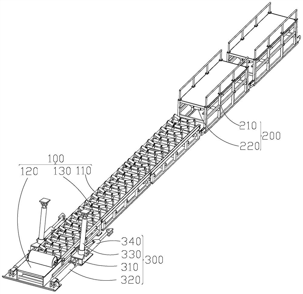
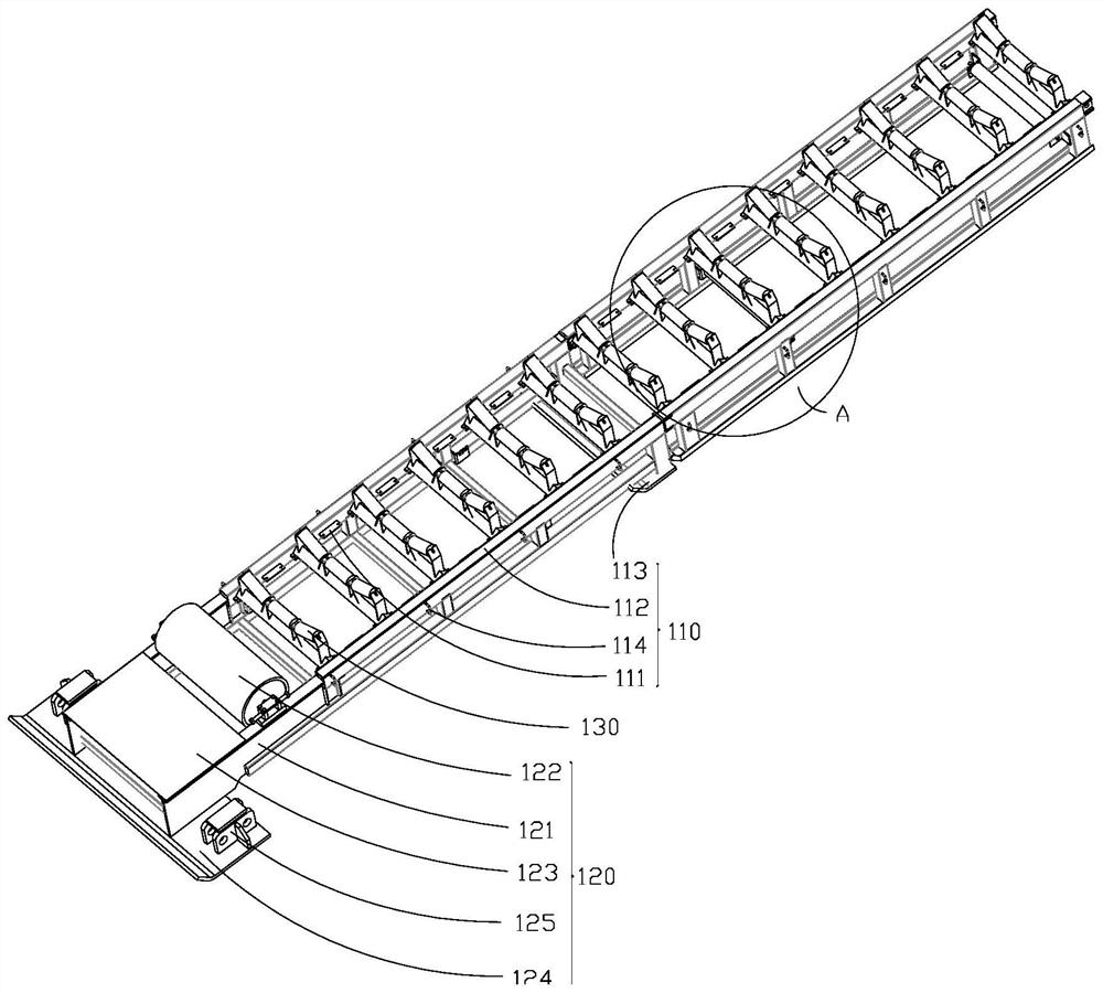
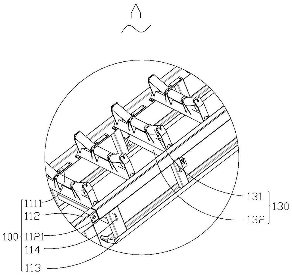
[0028] see figure 1 , an integrated belt conveyor tail device for mining, including a walking frame body 100, a conveying frame assembly 200, and a walking and supporting assembly 300, the walking frame body 100 and the conveying frame assembly 200 are detachably connected, the The walking and supporting assembly 300 is arranged on both sides of the walking frame body 100; the walking frame body 100 includes a number of supporting frames 110, a tail support 120 and a number of idlers, and each supporting frame 110 can be Disassemble the connection, the tail support 120 is arranged at the end of the support frame 110, the idler 130 is installed on the support frame 110, and is detachably connected with the support frame 110; during work, due to The idler member 130 continues to rotate d...


PUM


Abstract

The invention discloses an integrated belt conveyor tail device for mining, and belongs to the technical field of belt conveyors for mining. The device comprises a walking frame body, a conveying frame assembly and walking and supporting assemblies, the walking frame body is detachably connected with the conveying frame assembly, and the walking and supporting assemblies are arranged on the two sides of the walking frame body; and the walking frame body comprises several supporting frames, a tail supporting piece and several carrier roller pieces, the conveying frame assembly comprises several containing frames and several conveying frame carrier roller assemblies, and the walking and supporting assemblies comprise supporting sliding bases, front-driving telescopic mechanisms and upper supporting mechanisms. According to the device, the carrier roller pieces on the belt conveyor can be detachably connected and are convenient to replace; meanwhile, the device has a self-pushing function, manual dragging is avoided, and labor force is saved; and in addition, tools and other materials scattered in a mine tunnel can be collected, and the integrated belt conveyor tail device for mining has multiple functions.

Description

technical field [0001] The invention belongs to the technical field of belt conveyors for mining, and in particular relates to an integrated belt conveyor tail device for mining. Background technique [0002] At present, in the mining work in our country, the roadheader is usually used in conjunction with the belt conveyor, and the materials mined by the roadheader are transferred to the belt conveyor, and the material is transported by the belt conveyor. However, the function of the existing belt conveyor is relatively single, especially at the tail of the belt conveyor, which only plays the role of arranging the tail drum. At the same time, when the belt conveyor rollers are worn or damaged, it is difficult and time-consuming for the staff to replace the rollers. Laborious; moreover, in the mining process, the belt conveyor needs to be continuously pushed forward along the working face. The traditional method of moving and anchoring the belt conveyor is to use an anchor wi...

Claims


Application Information

Patent Timeline
IPC IPC(8): B65G39/12B65G23/44B65G21/06
CPCB65G39/12B65G23/44B65G21/06B65G2201/045
Inventor 张念生汪涛张永红杨海利石娜
Owner NINGXIA TIANDI BENNIU IND GRP
Learn More