Yarn feeder with adjustable yarn feeding speed

A yarn feeder and speed technology, used in textiles and papermaking, weft knitting, knitting, etc., can solve the problem of the complex structure of the yarn feeder, the lack of emphasis on the smoothness of the yarn feeding, and the manual adjustment of the yarn feeding speed. Axial fixation of the cylinder, etc., to achieve the effect of strong adjustability, simple structure and small volume

Active Publication Date: 2021-09-28
TIANJIN POLYTECHNIC UNIV
View PDF8 Cites 0 Cited by
  • Summary
  • Abstract
  • Description
  • Claims
  • Application Information

AI Technical Summary

Problems solved by technology

At present, there are many kinds of yarn feeders, which are often used in knitting equipment, and generally yarn feeders need to be equipped with motors and corresponding transmission mechanisms, which makes the structure of yarn feeders too complicated; the functions of traditional yarn feeders are mostly yarn storage and knot prevention. No emphasis on the stability of yarn feeding itself
The document with application number 201710741329.7 discloses an automatic yarn feeder, the driving device is a brushless DC motor with an outer rotor, and a rotating mover is set on the stator shaft, and the mover drives the yarn feeder to realize the yarn feeding function, but it does not consider Manual adjustment of yarn feeding speed and axial fixation of yarn feeding drum, which is the first step of yarn feeding tension control

Method used


Image

  • Yarn feeder with adjustable yarn feeding speed
  • Yarn feeder with adjustable yarn feeding speed
  • Yarn feeder with adjustable yarn feeding speed

Examples


Embodiment Construction

[0021] Specific examples of the present invention are given below. The specific embodiments are only used to further describe the present invention in detail, and do not limit the protection scope of the claims of the present application.

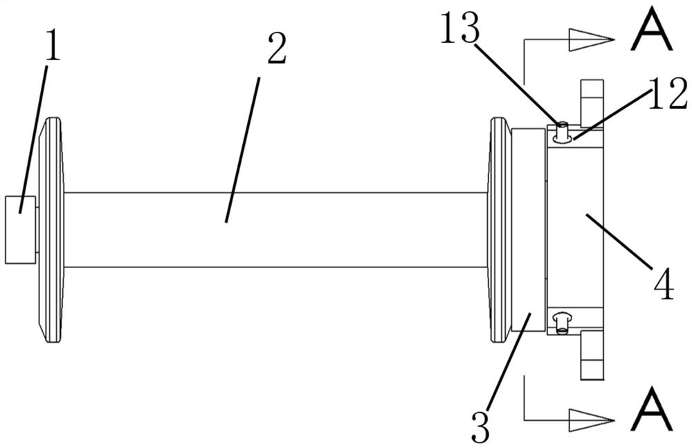
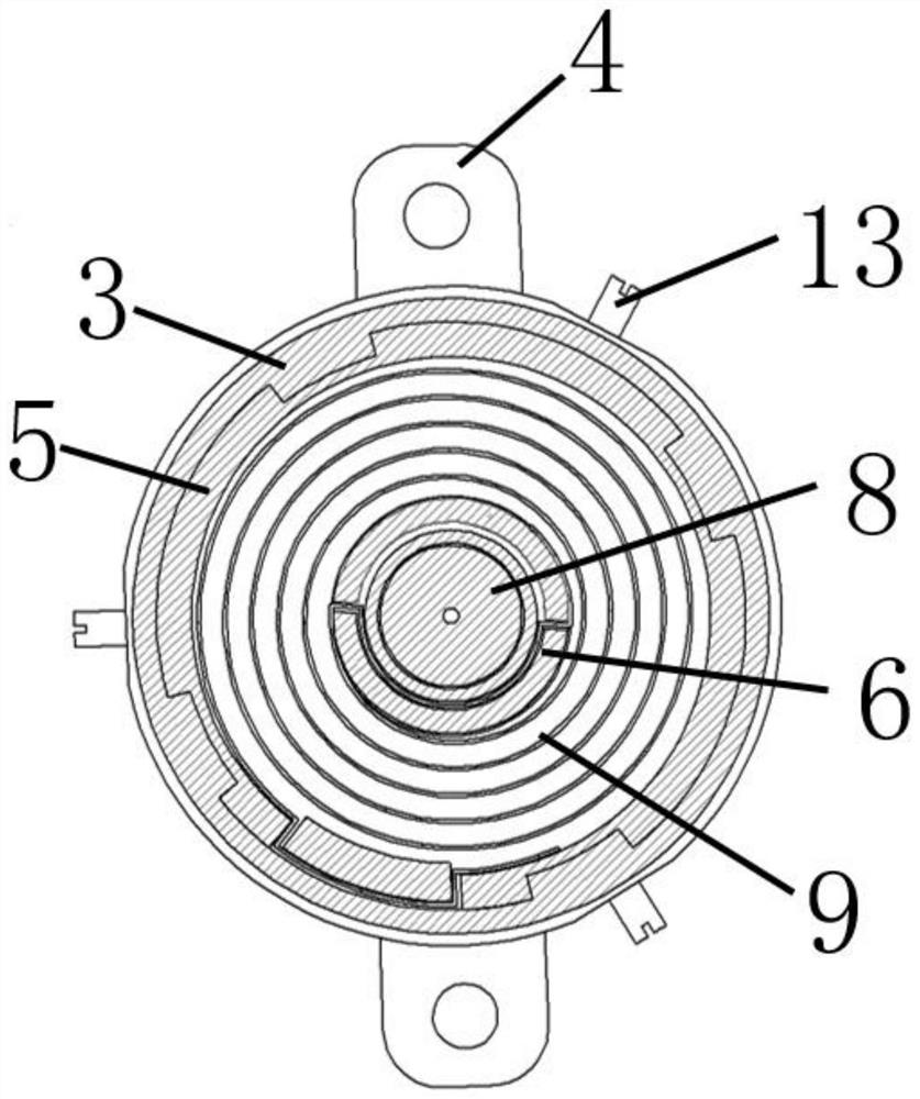
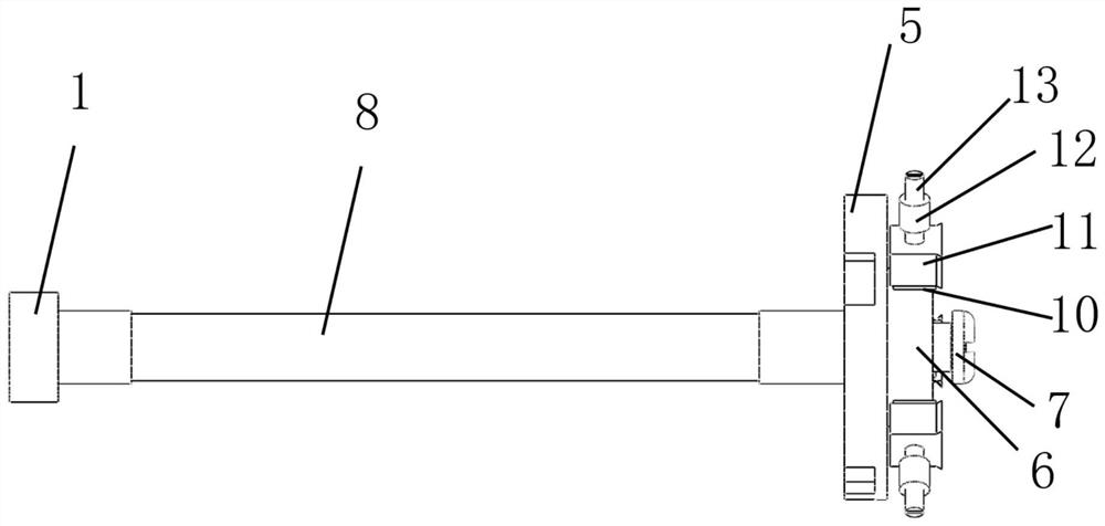
[0022] The present invention provides a yarn feeder with adjustable yarn feeding speed (short for yarn feeder), which is characterized in that the yarn feeder includes a terminal screw 1, a bobbin 2, a driven wheel cover 3, a bottom plate 4, and a driven wheel 5 , driving wheel 6, fixing screw 7, mandrel 8, coil spring 9, friction plate 11, insert block 12 and locking screw 13;

[0023] One end of the mandrel 8 is fixed on the base plate 4 by a fixing screw 7, and the other end is fixed with a head screw 1; the driving wheel 6 is located inside the base plate 4 and is mounted on the mandrel 8 by bearing rotation; the bobbin 2 is nested in the core The outer side of the shaft 8 is rotationally connected with the mandrel 8 through the bushin...


PUM


Abstract

The invention discloses a yarn feeder with the adjustable yarn feeding speed. The yarn feeder comprises an end screw, a bobbin, a driven wheel cover, a bottom plate, a driven wheel, a driving wheel, a mandrel, a coil spring, a friction plate, embedded blocks and a locking screw; one end of the mandrel is fixed on the bottom plate, and the end screw is fixed at the other end of the mandrel; the driving wheel is located in the bottom plate and rotationally installed on the mandrel; the bobbin is rotationally connected with the mandrel; one end of the bobbin is limited by the end screw, and the other end of the bobbin is fixedly connected with the driven wheel cover; the driven wheel cover is located on the outer side of the driven wheel and fixedly connected with the driven wheel; the driven wheel is rotationally mounted on the mandrel; the coil spring is arranged in the driven wheel, one end of the coil spring is fixedly connected with the driven wheel, and the other end of the coil spring is fixedly connected with the driving wheel; the plurality of embedded blocks are fixed on the bottom plate, and internal threads are formed in the embedded blocks; the friction plate is arranged at the tail end of the locking screw; and the locking screw is matched with the internal threads of the embedded blocks, and the friction plate at the tail end can make contact with the driving wheel. The yarn feeding tension and the yarn feeding speed can be manually adjusted.

Description

technical field [0001] The invention relates to the technical field of textiles, in particular to a yarn feeder with adjustable yarn feeding speed. Background technique [0002] Achieving good unwinding and yarn feeding of fiber bundles is the first step in the preparation of preforms, and continuous and stable yarn feeding is conducive to the formation and weaving of preforms. At present, there are many kinds of yarn feeders, which are often used in knitting equipment, and generally yarn feeders need to be equipped with motors and corresponding transmission mechanisms, which makes the structure of yarn feeders too complicated; the functions of traditional yarn feeders are mostly yarn storage and knot prevention. The stability of yarn feeding itself is not emphasized. The document with the application number 201710741329.7 discloses an automatic yarn feeder, the driving device is a brushless DC motor with an outer rotor, and a rotating mover is set on the stator shaft, and ...

Claims


Application Information

Patent Timeline
IPC IPC(8): D04B15/40D04B15/94D04B27/16D04B27/20D04B27/12D04B15/44
CPCD04B15/40D04B15/94D04B27/16D04B27/20D04B27/12D04B15/44
Inventor 陈利赵世波张一帆焦亚男陈小明
Owner TIANJIN POLYTECHNIC UNIV
Why Eureka
Try Eureka