Self-cleaning engine

An engine and self-cleaning technology, which is applied to machines/engines, cleaning hollow objects, cleaning methods and utensils, etc., can solve problems such as troublesome cleaning of carbon deposits in the engine, and achieve the effect of improving the cleaning effect, timely cleaning, and increasing the cleaning area.

Active Publication Date: 2021-09-28
WUXI YOUPENG AUTOMOBILE SERVICE
View PDF8 Cites 2 Cited by
  • Summary
  • Abstract
  • Description
  • Claims
  • Application Information

AI Technical Summary

Problems solved by technology

[0006] In order to make up for the deficiencies of the existing technology and solve the troublesome problem of engine carbon deposit cleaning, the present invention proposes a self-cleaning engine

Method used


Image

  • Self-cleaning engine
  • Self-cleaning engine
  • Self-cleaning engine

Examples


Embodiment 1

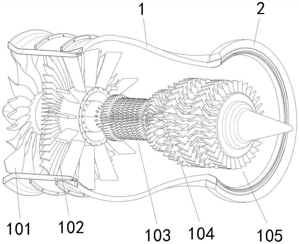
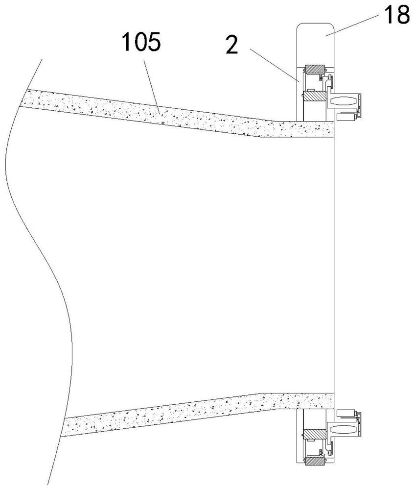
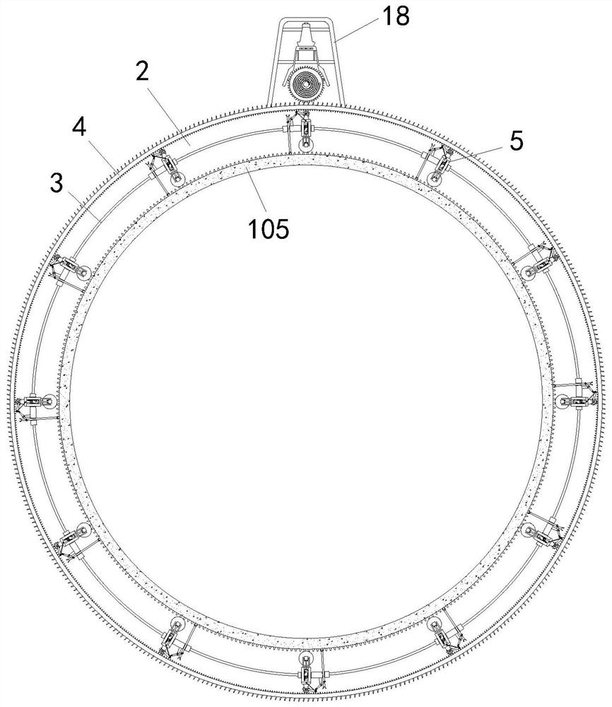
[0036] Such as Figure 1 to Figure 7 As shown, the self-cleaning engine of the present invention includes an engine main body 1 and a tail nozzle 105, a support ring 2 is fixedly installed on the outside of the tail nozzle 105, and a slidable movable seat 5 is installed inside the support ring 2, The bottom end of the movable seat 5 is provided with a cleaning brush 6. During work, under the initial state, the cleaning brush 6 is positioned at the outside of the tail nozzle 105, which will not affect the jet work of the tail nozzle 105. When cleaning, move the movable seat 5. Make the cleaning brush 6 move to contact with the inner wall of the tail nozzle 105, and then drive the cleaning brush 6 to roll along the inner wall of the tail nozzle 105, so as to remove the carbon deposit on the inner wall of the tail nozzle 105.

[0037] Described engine main body 1 comprises intake passage 101, compressor 102, combustion chamber 103, turbine mechanism 104, tail pipe 105 and accesso...

Embodiment 2

[0046] Such as Figure 8 to Figure 9 As shown in Comparative Example 1, another embodiment of the present invention is: a switch seat 24 is fixedly installed inside the main seat 18, a pressure ball 25 is placed inside the switch seat 24, and the inside of the switch seat 24 is located A baffle is arranged below the pressure ball 25, and a through hole corresponding to the pressure ball 25 is provided in the inside of the baffle, and the diameter of the through hole is smaller than the diameter of the pressure ball 25. 25 corresponds to the arm bar 26, the end portion 26 of the arm bar is inserted below the pressure ball 25, and the end portion 26 of the arm bar is located above the baffle plate, and the bottom end of the switch base 24 is provided with a switch for controlling the spring assembly 20 Key 27, switch key 27 is positioned at the below of touch pressure ball 25, and during work, switch key 27 is used for controlling the locking and activity of clockwork assembly 2...


PUM


Abstract

The invention belongs to the field of engines and particularly relates to a self-cleaning engine. The self-cleaning engine comprises an engine main body and an exhaust nozzle, wherein a supporting ring is fixedly mounted on the outer side of the exhaust nozzle; a slidable and movable seat is mounted in the supporting ring; a cleaning brush is mounted at the bottom end of the movable seat; an inner rotating ring and an outer rotating ring are rotatably mounted in the supporting ring; a control panel is movably inserted into the inner rotating ring; a one-way ratchet wheel in meshed connection with the outer rotating ring is rotatably mounted in a main base; a spring assembly is mounted on the one-way ratchet wheel; when the movable seat moves, a fixed toothed plate and an intermediate gear are used for driving a movable toothed plate to move downwards; the movable toothed plate drives the cleaning brush to move into the exhaust nozzle through the connecting plate; the cleaning brush can be in full contact with the inner wall of the exhaust nozzle; the cleaning area is increased; a pendulum gyroscope is arranged and is used for sensing vibration and swing of the engine main body; a function of automatically removing the deposited carbon when the engine does not work is achieved, and the deposited carbon is cleaned timely; meanwhile, manual operation is not needed; and the self-cleaning engine is convenient to use.

Description

technical field [0001] The invention belongs to the field of engines, in particular to a self-cleaning engine. Background technique [0002] The engine is an important power propulsion device in the fields of automobiles and aviation. Common engines include turbojet engines and turbofan engines. Engines are generally composed of intake ports, compressors, combustion chambers, turbines and exhaust nozzles. The air enters the engine from the intake port, and after the compression process, isobaric heating process, expansion process and isobaric heat release process, it is ejected at high speed from the tail nozzle to generate the kinetic energy of high-speed jet flow. The engine uses fossil fuels as energy sources , After working for a long time, there will be a problem of carbon deposits on the valve. Carbon deposits refer to the colloidal deposits produced when the fuel is not completely burned. It will also lead to higher fuel consumption. [0003] There are also some tec...

Claims


Application Information

Patent Timeline
Patent Type & Authority Applications(China)
IPC IPC(8): F02K3/00F02K1/78B08B9/045
CPCF02K3/00F02K1/78B08B9/045
Inventor 郭大聪李健朱峰姜鑫吴正
Owner WUXI YOUPENG AUTOMOBILE SERVICE
Why Eureka
Try Eureka