
Umbrella type drying equipment for glass test tubes

A drying equipment and drying technology, applied in drying chamber/container, drying gas arrangement, local stirring dryer, etc., to achieve the effect of improving drying efficiency and being less prone to damage

Active Publication Date: 2021-09-28
HAIMENCITY KAHOTEST CITOTEST LABWARE MFG
View PDF6 Cites 2 Cited by
  • Summary
  • Abstract
  • Description
  • Claims
  • Application Information

AI Technical Summary

Problems solved by technology

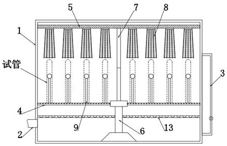
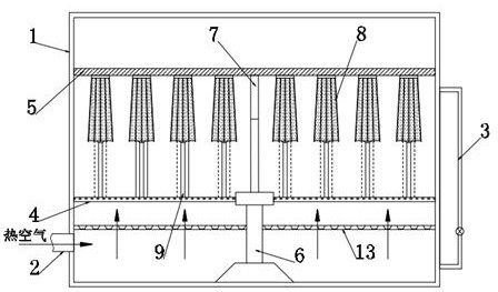
[0005] Aiming at the problems existing in the prior art, the object of the present invention is to provide a glass test tube umbrella-type drying equipment, which is set through the cooperation of the air-free tray and the air-expand umbrella. When drying, the air-expand umbrella cover is arranged on the air-free tray On the outside of the test tube, under the action of hot air from bottom to top, the air umbrella expands outwards and separates from the outer surface of the test tube, and forms a protective ring on the outside of the test tube to effectively protect the test tube and make it less likely to occur during rotation without the wind tray Large displacement, compared with the existing technology, effectively avoids the occurrence of uneven drying due to the existence of the fixing parts, making it difficult to produce marks on the outer surface of the test tube after drying, and at the same time, when drying, the inside of the air exhibition umbrella changes. The strip expands under the action of hot air. At this time, part of the hot air inside the air-varying seal overflows along its surface and blows directly on the surface of the test tube, which significantly improves the drying efficiency of the test tube.

Method used


Image

  • Umbrella type drying equipment for glass test tubes
  • Umbrella type drying equipment for glass test tubes
  • Umbrella type drying equipment for glass test tubes

Examples


Embodiment 1

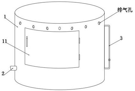
[0042] see Figure 1-2 , a glass test tube umbrella type drying equipment, comprising a drying shell 1, the lower left end of the drying shell 1 is fixedly connected with a vent pipe 2, the vent pipe 2 communicates with the drying shell 1, and the inside of the drying shell 1 is fixedly connected with a porous air plate 13, and the porous air The plate 13 is located above the ventilation pipe 2. After the hot air is passed into the drying shell 1 from the ventilation pipe 2, it needs to move upward along the pores on the porous air plate 13, thereby forming a hot air flow from bottom to top, and controlling the flow of hot air. The temperature is 35-50°C, which is convenient for the air-expanding umbrella 8 to expand outwards. The outer end of the drying shell 1 is connected with a sealed door 11. The transverse span of the sealed door 11 is not less than 1 / 3 of the diameter of the drying shell 1, which is convenient for placing the test tube in the The operation on the inner ...


PUM


Abstract

The invention discloses umbrella type drying equipment for glass test tubes, and belongs to the field of test tube drying. Through cooperative arrangement of a non-air-receiving disc and air spreading umbrellas, during drying, the air spreading umbrellas are arranged on the outer sides of the test tubes on the non-air-receiving disc. Under the action of hot air from bottom to top, the air spreading umbrellas expand outwards and are separated from the outer surfaces of the test tubes, and form protection rings on the outer sides of the test tubes to effectively protect the test tubes, so that the test tubes are not prone to large displacement in the rotating process of the non-air-receiving disc. Compared with the prior art, the situation that drying is not uniform due to the existence of a fixing piece is effectively avoided, and marks are not prone to being generated after the outer surfaces of the test tubes are dried; and meanwhile, during drying, the variable air sealing strips in the air spreading umbrellas expand under the action of the hot air, and part of hot air in the variable air sealing strips overflows along the surfaces of the variable air sealing strips to be directly blown to the surfaces of the test tubes at the moment, so that the drying efficiency of the test tubes is remarkably improved.

Description

technical field [0001] The invention relates to the field of test tube drying, in particular to a glass test tube umbrella drying equipment. Background technique [0002] Test tube, a commonly used instrument in the laboratory, is used as a reaction container for a small amount of reagents. It is used at room temperature or when heated (it should be preheated before heating, otherwise the test tube is easy to burst). Test tubes are divided into ordinary test tubes, support test tubes, centrifuge test tubes and so on. [0003] In the prior art, when the test tube is dried after cleaning, it is generally placed upside down on a wooden test tube rack to allow it to air dry naturally, or the test tube is first fixed and then dried by flowing hot air, but the first method of drying The efficiency is low, and in the second method, the part of the test tube in contact with the fixing part is blocked by the fixing part, resulting in uneven drying, and after drying, there is a certa...

Claims


Application Information

Patent Timeline
IPC IPC(8): F26B9/10F26B21/10F26B25/08F26B25/18
CPCF26B9/10F26B21/001F26B21/004F26B21/10F26B25/08F26B25/18
Inventor 董红星
Owner HAIMENCITY KAHOTEST CITOTEST LABWARE MFG
Learn More