Method for manufacturing shielded wire harness

A manufacturing method and technology for shielded wires, which are applied in cable/conductor manufacturing, electrical components, circuits, etc., can solve problems such as poor work efficiency, and achieve the effects of improving workability, optimizing efficiency, and improving personnel allocation.

Pending Publication Date: 2021-09-28
FURUKAWA ELECTRIC CO LTD +1
View PDF2 Cites 0 Cited by
  • Summary
  • Abstract
  • Description
  • Claims
  • Application Information

AI Technical Summary

Problems solved by technology

However, since the above-mentioned work is performed while changing the direction and position of the long wire harness, the work efficiency is poor.

Method used


Image

  • Method for manufacturing shielded wire harness
  • Method for manufacturing shielded wire harness
  • Method for manufacturing shielded wire harness

Examples


Embodiment Construction

[0053] Hereinafter, embodiments of the present invention will be described in detail with reference to the drawings.

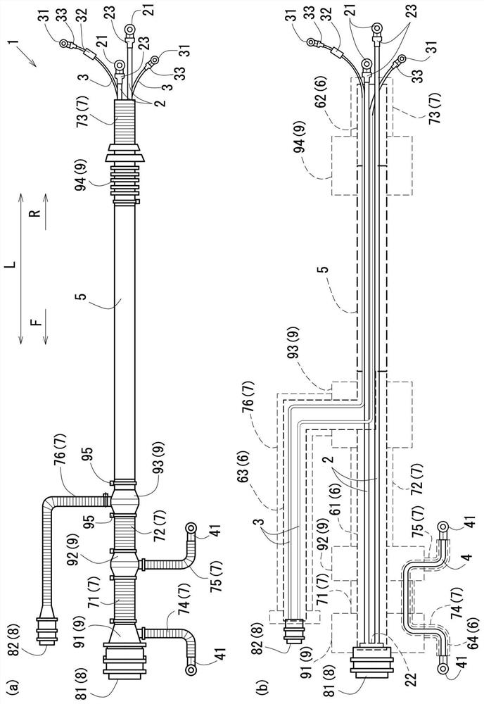
[0054] In addition, each figure will be described below, and the figure 1 , Figure 4 , Figure 6 (a), (b), (e), (f), Figure 7 , Figure 10 , Figure 14 , Figure 17 In (a), (b), and (d), the left side is defined as the front side F, and the right side is defined as the rear side R.

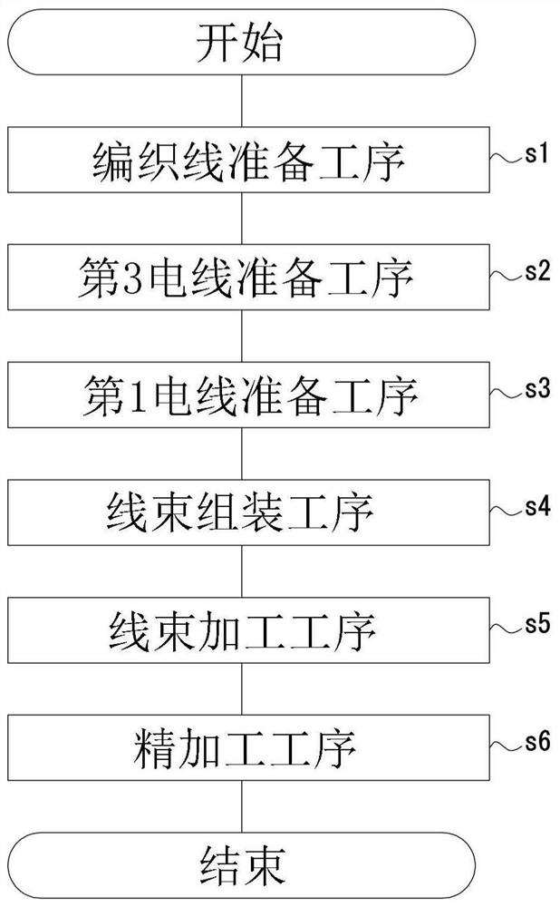
[0055] figure 1 (a) shows a schematic diagram of the shielded wire harness 1 . figure 1 (b) shows a schematic diagram of the shielded wire harness 1 showing the braided wire 6 , the corrugated tube 7 , the connector 8 , and the grommet 9 in a see-through state. In addition, in figure 1 In (b), the bellows 7, the connector 8, and the grommet 9 are schematically shown by dotted lines. figure 2 The overall schematic flowchart of the manufacturing method of the shielded wire harness 1 is shown.

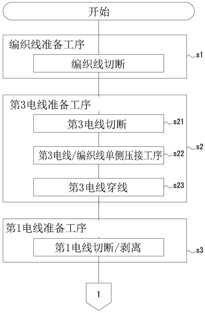
[0056] image 3 The schematic flowchart of the braided wire preparation pr...


PUM


Abstract

The object of the present invention is to provide a method for manufacturing a shielded wire harness capable of efficiently manufacturing the shielded wire harness of a cable so that at least a part of theshielded wire harness is inserted into theelectromagnetic shielded multilayer tube and the rest is covered by abraided wire which is electrically connected with theelectromagnetic shielded multilayer tube. In a first wire threading/combining process (step s41), a first wire (2) is inserted into the braided wire (6). The method also comprises a handle installation process (step s51) and a wire harness processing process (step s5). In the step of pressing the braided wire of the electromagnetic shielding multilayer tube (step s52) in the wire harness processing step (step s5), The position of a handle (10) attached to a fixed part (110) of a braided thread pressing work table (100) is restricted for processing.

Description

technical field [0001] The present invention relates to a method of manufacturing a shielded wire harness. For example, at least a part of the wire and cable length direction of the shielded wire harness is inserted through a cylindrical electromagnetic shielding multilayer tube, and the other part is covered with a braided wire. The electromagnetic shielding multilayer tube is electrically connected. Background technique [0002] For example, wires connecting electrical equipment such as an inverter device and a motor in a hybrid car or an electric car are sometimes placed under the floor of the car body depending on the shape of the car body, and it is necessary to prevent damage caused by flying stones or the like. In addition, it is also necessary to prevent malfunction of mounted electronic devices due to noise by blocking radiation of noise generated from electric wires and intrusion of noise from the outside. [0003] Therefore, for example, Patent Document 1 disclos...

Claims


Application Information

Patent Timeline
Patent Type & Authority Applications(China)
IPC IPC(8): H01B13/22
CPCH01B13/22H01B13/224
Inventor 水野博贵川村俊博汤浅辰哉堀池和德山崎正则鸟本幸宏中川健安本豪斗生田政幸中关隆仁今村文仁
Owner FURUKAWA ELECTRIC CO LTD
Why Eureka
Try Eureka