
Lithium battery liquid injection head

A lithium battery injection, lithium battery technology, applied in battery pack parts, secondary battery gas removal, secondary battery repair/maintenance, etc., can solve the problem of low negative pressure rate, high injection volume, electrolyte waste, etc. problems, to achieve the effect of less component composition, high injection efficiency, and good injection effect.

Pending Publication Date: 2021-09-28
HUIZHOU DUOKEDA TECH
View PDF0 Cites 0 Cited by
  • Summary
  • Abstract
  • Description
  • Claims
  • Application Information

AI Technical Summary

Problems solved by technology

When this method is used for liquid injection, it has the following disadvantages: 1. The electrolyte is taken away by the steel case and cap surface of the lithium battery more, resulting in a waste of electrolyte; 2. The surface of the lithium battery is easily corroded, which affects the appearance of the lithium battery. Beautiful; 3. Manually put the battery into the electrolyte and take it out of the electrolyte, it takes a long time and the efficiency is low
However, it uses vacuum equipment to evacuate the whole battery or battery pack at the same time, and the vacuuming volume of each battery is inconsistent, resulting in uneven negative pressure in each battery during the liquid injection process, and the negative pressure rate is low, which leads to the injection of each battery. There is a problem of inconsistent high and low liquid volume
For batteries with a high negative pressure rate, the liquid injection volume will be too high, and even overflow the surface of the battery, causing corrosion to the battery
For batteries with a low negative pressure rate, the liquid injection volume will be too low, resulting in insufficient liquid injection in the battery

Method used


Image

  • Lithium battery liquid injection head
  • Lithium battery liquid injection head
  • Lithium battery liquid injection head

Examples


Embodiment Construction

[0023] The lithium battery liquid injection head of the present invention will be further described in detail below in conjunction with specific embodiments and accompanying drawings.

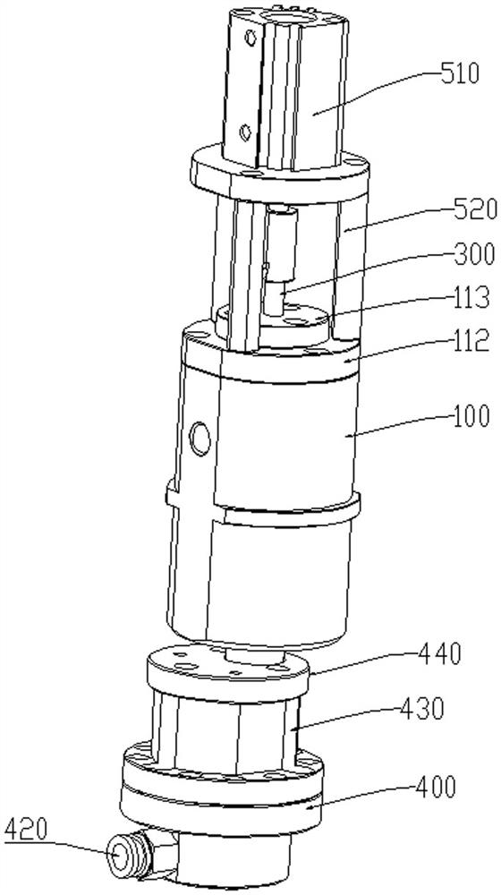
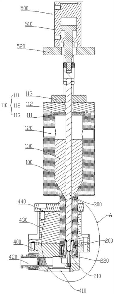
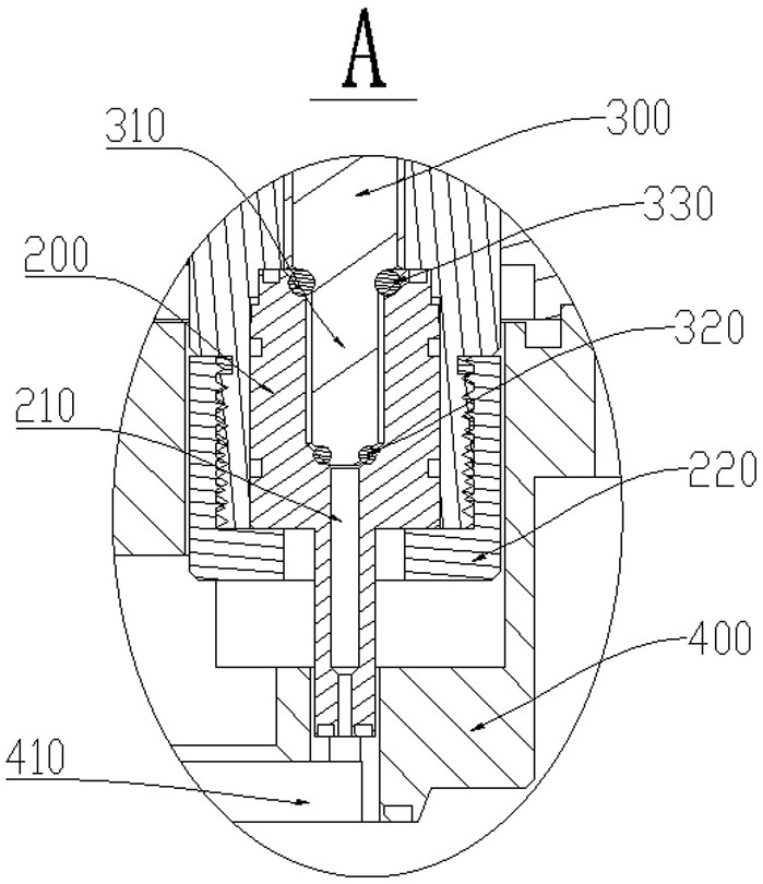
[0024] refer to Figure 1 to Figure 3 , a non-limiting embodiment of the present invention, a lithium battery liquid injection head, including a liquid injection cavity 100, one end of the liquid injection cavity 100 is a sealing end, the other end is a liquid injection end, and the inside of the liquid injection end Equipped with a liquid injection needle 200, the liquid injection needle 200 communicates with the liquid injection cavity 100, a vacuum cavity 400 is installed on the outside of the liquid injection end, and the outer end of the vacuum cavity 400 is provided with a lithium battery The battery tank 410 of the liquid injection needle 200 corresponds to the position of the liquid injection hole on the lithium battery, and the liquid injection needle 200 communicates with the vacuum c...


PUM


Abstract

The invention relates to a lithium battery liquid injection head, and the injection head comprises a liquid injection cavity, wherein one end of the liquid injection cavity is a sealed end, the other end of the liquid injection cavity is a liquid injection end, a liquid injection needle is installed in the liquid injection end and communicated with the interior of the liquid injection cavity, a vacuum cavity is installed outside the liquid injection end, a battery jar for accommodating a lithium battery is arranged at the outer end part of the vacuum cavity, a liquid outlet head of the liquid injection needle corresponds to a liquid injection hole in the lithium battery in position, and the liquid injection needle is communicated with the interior of the vacuum cavity; a liquid injection sealing rod used for sealing the liquid injection needle is arranged in the liquid injection cavity, and a driving piece is arranged at the outer end of the liquid injection sealing rod. The lithium battery liquid injection head has the advantages of simple structure, high liquid injection efficiency, good liquid injection effect and the like.

Description

technical field [0001] The invention relates to the technical field of liquid injection for lithium batteries, in particular to a liquid injection head for lithium batteries. Background technique [0002] For the liquid injection operation of lithium batteries, at present, the traditional vacuum suction liquid injection is mainly used, that is, the lithium battery is placed upside down in the electrolyte by manual operation, and the air in it is pumped out, and the electrolyte enters the lithium battery under the action of atmospheric pressure. battery. When this method is used for liquid injection, it has the following disadvantages: 1. The electrolyte is taken away by the steel case and cap surface of the lithium battery more, resulting in a waste of electrolyte; 2. The surface of the lithium battery is easily corroded, which affects the appearance of the lithium battery. Beautiful; 3. Putting the battery into the electrolyte and taking it out of the electrolyte by manual...

Claims


Application Information

Patent Timeline
Patent Type & Authority Applications(China)
IPC IPC(8): H01M50/609H01M10/52
CPCH01M10/52Y02E60/10
Inventor 吴家军
Owner HUIZHOU DUOKEDA TECH
Learn More