Motor control method, corresponding projection structure, vehicle lamp and vehicle

A technology of projection and car lights, which is applied in the field of projection, can solve the problems of prolonging cycle time and unsatisfactory projection effect, and achieve the effect of reducing delay, improving projection quality, and avoiding blurred images

Pending Publication Date: 2021-09-28
VALEO ICHIKOH CHINA AUTO LIGHTING
View PDF0 Cites 0 Cited by
  • Summary
  • Abstract
  • Description
  • Claims
  • Application Information

AI Technical Summary

Problems solved by technology

This increases cycle time and also results in less than ideal projection

Method used


Image

  • Motor control method, corresponding projection structure, vehicle lamp and vehicle
  • Motor control method, corresponding projection structure, vehicle lamp and vehicle
  • Motor control method, corresponding projection structure, vehicle lamp and vehicle

Examples


Embodiment Construction

[0039] Preferred embodiments of the present invention will be described in more detail below with reference to the accompanying drawings. Although preferred embodiments of the invention are shown in the drawings, it should be understood that the invention may be embodied in various forms and should not be limited to the embodiments set forth herein. Rather, these embodiments are provided so that this disclosure will be thorough and complete, and will fully convey the scope of the invention to those skilled in the art.

[0040] Embodiments of the present invention disclose a projection structure and a method for projection, as well as a vehicle lamp with the projection structure and a vehicle using the vehicle lamp.

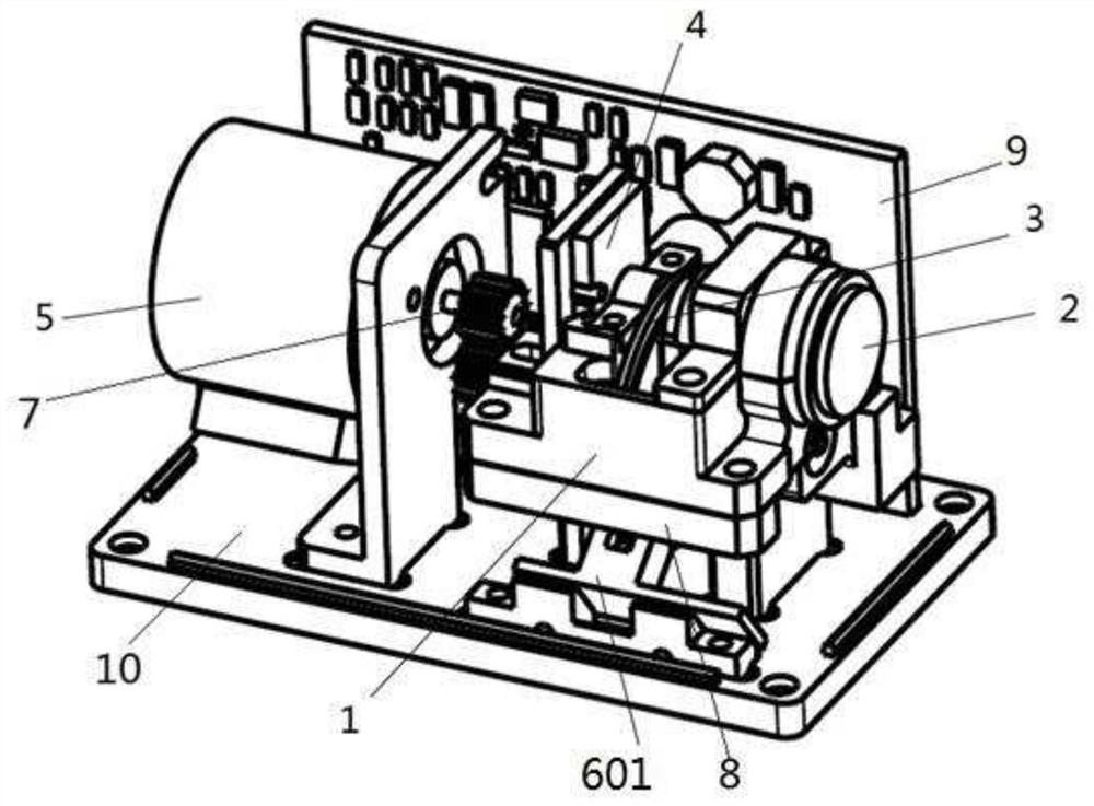
[0041] Among them, refer to figure 1 . figure 1 A three-dimensional schematic diagram of a projection structure according to an embodiment of the present invention is shown.

[0042] according to figure 1 The projection structure of the illustrated embodime...


PUM


Abstract

One of the problems solved by the embodiment of the invention is to reduce the delay when the motor stops. The invention provides a control method, a corresponding projection structure, a vehicle lamp and a vehicle. The motor provided by the invention is provided with a control part, and the method comprises the steps that the control part outputs current to the motor based on a current pulse period so as to control the rotation of the motor, wherein the current pulse period comprises a motion period, a transition period and an interval period, and the motion period enters the interval period after passing through the transition period. The method has the advantages that power is not provided for the motor any more before the motor reaches the target position in the transition period, the motor directly stops at the target position through inertia, delay caused by overshoot of the motor is reduced, and the projection quality is improved due to the fact that fuzzy images caused in the rotation process of the projection motor are avoided.

Description

technical field [0001] The invention relates to the field of projection technology, in particular to a motor control method, a projection structure, and a corresponding lamp and vehicle. Background technique [0002] When a stepper motor is used to realize projection control, the motor needs to rotate and stop periodically. Due to inertia, the motor will oscillate back and forth after receiving the stop signal, and it will take a certain delay time to actually stop at the target position. refer to figure 2 and image 3 . For the current waveform shown in Figure 2, its corresponding image 3 The schematic diagram of the rotation is shown. When the current outputs a complete sine wave, the motor rotor turns from the initial position S to the target position D, and then the current becomes a constant flat wave. At this time, due to inertia, the rotor swings back and forth near the target position D, which takes a period of time After that, it is really stable at the target...

Claims


Application Information

Patent Timeline
IPC IPC(8): H02P8/12H02P8/30G03B21/14
CPCH02P8/12H02P8/30G03B21/14
Inventor 陈海泉成崟峰吴昌琦
Owner VALEO ICHIKOH CHINA AUTO LIGHTING
Why Eureka
Try Eureka