Plate uncoiling and shearing die

A mold and sheet technology, applied in the field of shearing mold tooling, can solve the problems of increasing mold maintenance costs, easy deformation of feeding rollers, and cutting damage of non-metallic rollers, so as to reduce mold maintenance costs and avoid scratches. The effect of damage and avoidance of crushing and deformation

Active Publication Date: 2021-10-01
DONGFENG AUTOMOBILE COMPANY
View PDF7 Cites 1 Cited by
  • Summary
  • Abstract
  • Description
  • Claims
  • Application Information

AI Technical Summary

Problems solved by technology

[0002] Uncoiling and blanking automatic production lines are widely used in automobile sheet production lines. In the process of cutting coils into sheets, due to the weight of the coils themselves, the coils tend to bend downward during the feeding process, resulting in scraping and shearing. The cutting edge of the tool will cause scratches on the sheet; at the same time, during the cutting process, some feed rollers that are squeezed by the upper blade are easy to deform, and the irregularly shaped rollers after deformation are also likely to cause scratches on the

Method used


Image

  • Plate uncoiling and shearing die
  • Plate uncoiling and shearing die
  • Plate uncoiling and shearing die

Examples


Embodiment 1

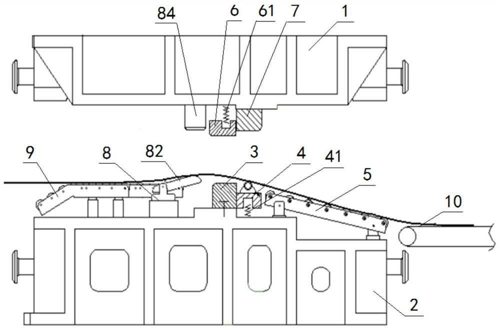
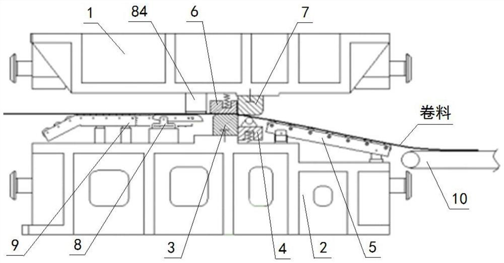
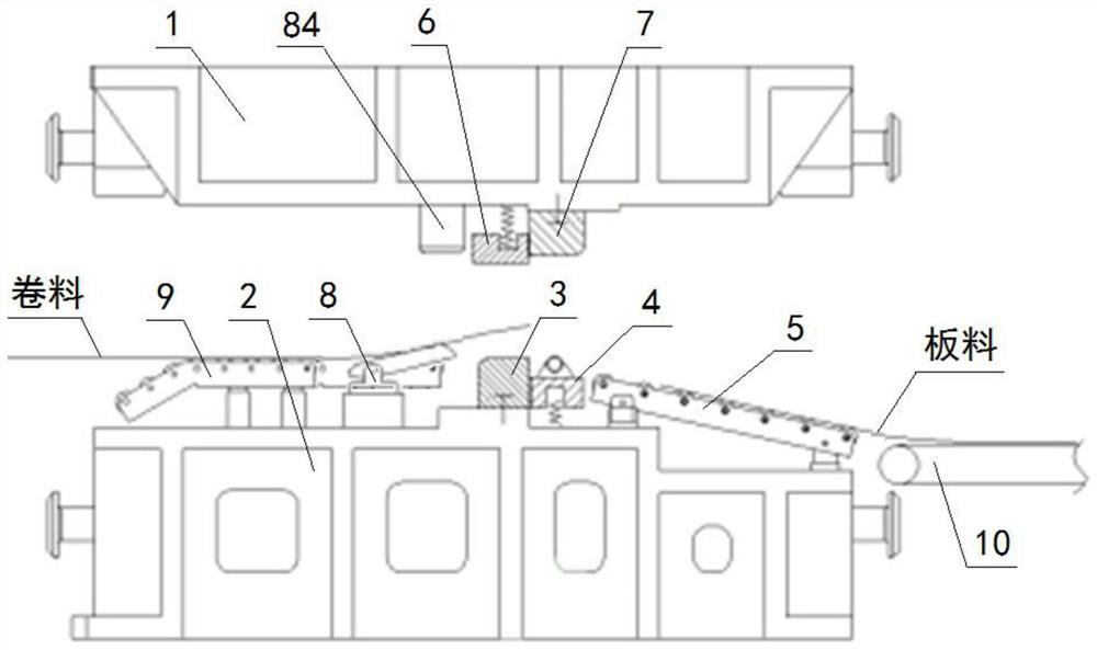
[0078] A sheet material uncoiling and shearing die, the sheet material uncoiling and shearing die comprises: an upper die base 1 and a lower die base 2, the upper die base 1 is located above the lower die base 2, the upper die base 1 and the lower die base The base 2 is matched; the top of the lower mold base 2 is sequentially provided with a lower mold knife block 3, an elastic support frame 4 and a discharge roller bar group 5 from the feed side to the discharge side; the lower mold knife block 3 It is fixedly arranged on the lower die base 2, and an elastic presser 6 is correspondingly arranged directly above the lower die block 3, and the top of the elastic presser 6 is connected to the bottom of the upper die base 1 through a presser spring 61 , the bottom of the elastic presser 6 is press fit with the top of the lower die block 3; the bottom of the elastic bracket 4 is connected with the top of the lower mold base 2 by the bracket spring 41, and the elastic bracket 4 Cor...

Embodiment 2

[0080] Embodiment 2 is basically the same as Embodiment 1, and its difference is:

[0081]The elastic bracket 4 includes a roller seat 43 and a circular rolling body 42, and the rolling body 42 is arranged on the top of the roller seat 43; the bracket spring 41 includes a first bracket spring 411 and a first bracket spring 411. The second bracket spring 412, the bottom of the first bracket spring 411 is connected with the top of the lower mold base 2, and the top of the first bracket spring 411 is connected with one end of the roller seat 43, said The other end of the roller seat 43 is connected with the top of the second bracket spring 412, and the bottom of the second bracket spring 412 is connected with the top of the lower mold base 2; Each end is fixed with a spacer 44, and the spacer 44 is press fit with the corresponding boss 11 on the upper mold base 1; the roller seat 43 is provided with a guide screw 45, and the guide screw 45 The upper end of the guide screw 45 is ...

Embodiment 3

[0083] Embodiment 3 is basically the same as Embodiment 2, and its difference is:

[0084] The rolling elements 42 are two cylindrical roller shafts 47, the two ends of each of the roller shafts 47 are respectively connected to the top of the roller seat 43 through a roller bracket 46, and the roller shafts 47 and the two ends of the roller shafts 47 are The roller support 46 is rotated and matched; the two ends of the top of the lower mold base 2 are respectively provided with two guide pillars 23, and the sides of the guide pillars 23 are provided with a storage limit column 24, and the storage limit column 24 is fixed on the lower On the die base 2; the two ends of the top of the lower die base 2 are each fixedly provided with a slide bar 21, and the slide bar 21 is positioned at the far side of the lower mold knife block 3 of the rotating supporting device 8, and the slide bar 21 The upper sleeve is provided with a limit block 22 , and the limit block 22 is slidingly match...


PUM


Abstract

A plate uncoiling and shearing die comprises an upper die base and a lower die base. A lower die cutter block, an elastic material supporting frame and a discharging roller strip set are sequentially arranged on the top of the lower die base from the feeding side to the discharging side. The lower die cutter block and the discharging roller strip set are fixed to the lower die base, an elastic material pressing device is correspondingly arranged over the lower die cutter block, the top of the elastic material pressing device is connected with the bottom of the upper die base through a material pressing device spring, and the bottom of the elastic material pressing device is matched with the top of the lower die cutter block in a pressing mode. The bottom of the elastic material supporting frame is connected with the top of the lower die base through a material supporting frame spring, an upper die cutter block is correspondingly arranged over the elastic material supporting frame, the top of the upper die cutter block is fixedly connected with the bottom of the upper die base, and the upper die cutter block is matched with the lower die cutter block. According to the design, roll materials are prevented from being scratched by a cutting edge of the lower die cutter block, meanwhile, the die is prevented from being damaged by the edges of the roll materials, and the die maintenance cost is reduced.

Description

technical field [0001] The invention relates to a shearing die tooling, in particular to a sheet material uncoiling shearing die, which is particularly suitable for sheet material shearing. Background technique [0002] Uncoiling and blanking automatic production lines are widely used in automobile sheet production lines. In the process of cutting coils into sheets, due to the weight of the coils themselves, the coils tend to bend downward during the feeding process, resulting in scraping and shearing. The cutting edge of the tool will cause scratches on the sheet; at the same time, during the cutting process, some feed rollers that are squeezed by the upper blade are easy to deform, and the irregularly shaped rollers after deformation are also likely to cause scratches on the sheet. To prevent the roller from scratching the sheet, you can choose a softer non-metallic feeding roller, but the use of a softer non-metallic roller has caused a new problem, that is, when the shee...

Claims


Application Information

Patent Timeline
IPC IPC(8): B21D28/14B21D43/08B21D43/14B21D45/00
CPCB21D28/14B21D43/08B21D43/14B21D45/00
Inventor 吴洁唐剑锋李晋忠郝军伟王南艳
Owner DONGFENG AUTOMOBILE COMPANY
Why Eureka
Try Eureka