
Stray light absorption device

A technology for absorbing devices and stray light, applied in laser welding equipment, welding equipment, metal processing equipment, etc.

Pending Publication Date: 2021-10-01
上海波刺自动化科技有限公司
View PDF0 Cites 0 Cited by
  • Summary
  • Abstract
  • Description
  • Claims
  • Application Information

AI Technical Summary

Problems solved by technology

[0004] The purpose of the present invention is to provide a stray light absorbing device to solve the problem that better carbon steel cutting surface quality and faster stainless steel cutting speed cannot be combined on one laser cutting head

Method used

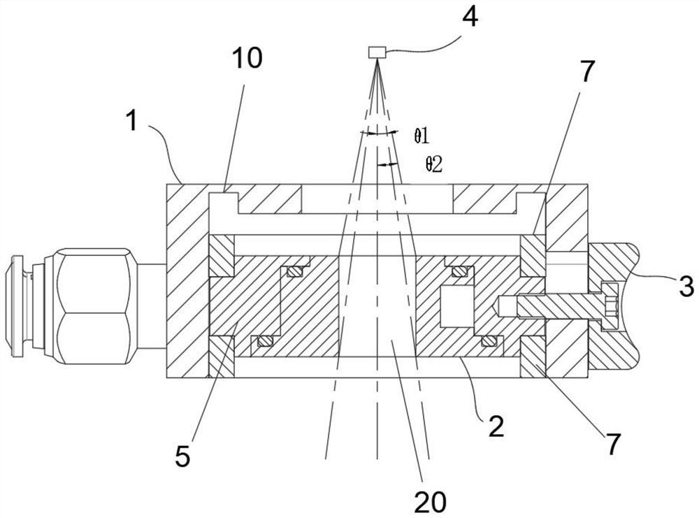
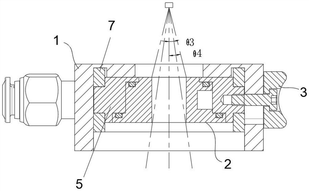

Image

  • Stray light absorption device
  • Stray light absorption device
  • Stray light absorption device

Examples


Embodiment Construction

[0049] The present invention will be further described in detail below in conjunction with the accompanying drawings and embodiments. It should be understood that the specific embodiments described here are only used to explain the present invention, but not to limit the present invention. In addition, it should be noted that, for the convenience of description, only some structures related to the present invention are shown in the drawings but not all structures.

[0050] In the description of the present invention, unless otherwise clearly specified and limited, the terms "connected", "connected" and "fixed" should be understood in a broad sense, for example, it can be a fixed connection, a detachable connection, or an integrated ; It can be a mechanical connection or an electrical connection; it can be a direct connection or an indirect connection through an intermediary, and it can be the internal communication of two components or the interaction relationship between two ...


PUM


Abstract

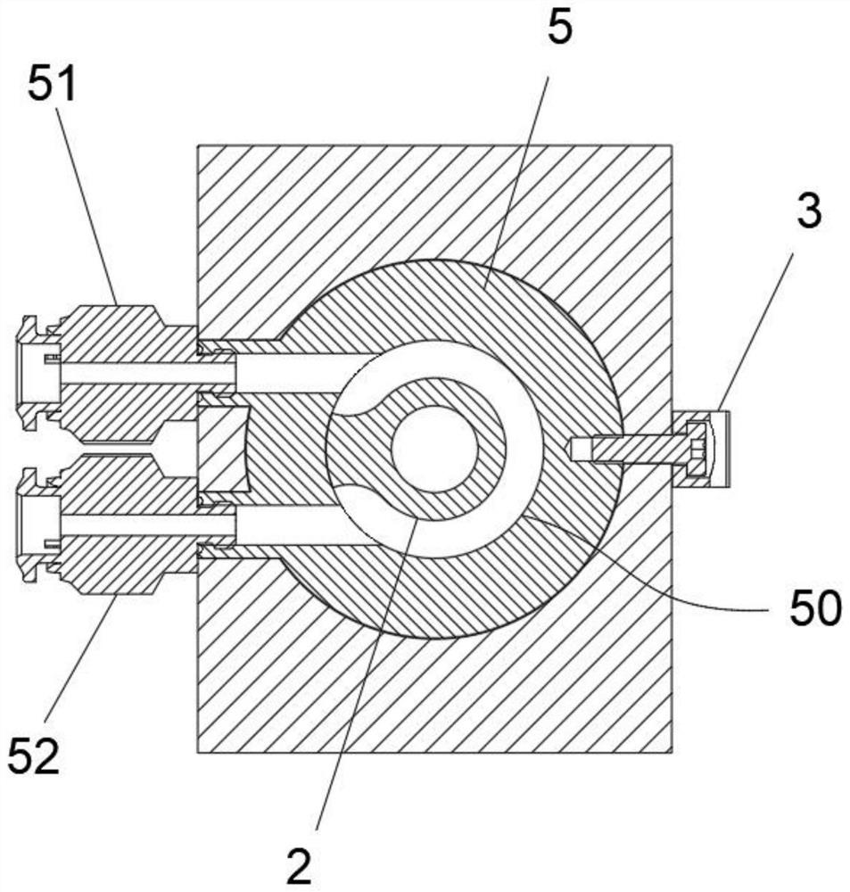
The invention belongs to the technical field of laser cutting devices, and discloses a stray light absorption device. The device comprises a fixed seat with an inner cavity, a stray light absorption unit and a pushing unit, wherein the top end of the inner cavity is provided with a light inlet hole; the stray light absorption unit is provided with an absorption cavity; the pushing unit drives the stray light absorption unit to move between a first position and a second position, and when the stray light absorption unit is located at the first position, a minimum absorption angle in a high stray light absorption rate state is formed between the first end of the absorption cavity and a light source; a maximum absorption angle in a high stray light absorption rate state is formed between the second end of the absorption cavity and the light source; and when the stray light absorption unit is at the second position, a minimum absorption angle in a low stray light absorption rate state is formed between the first end of the absorption cavity and the light source, and a maximum absorption angle in the low stray light absorption rate state is formed between the second end of the absorption cavity and the light source. Two requirements of carbon steel cutting and stainless steel cutting can be met on the same laser cutting head.

Description

technical field [0001] The invention relates to the technical field of laser cutting devices, in particular to a stray light absorbing device. Background technique [0002] Carbon steel cutting uses laser-assisted oxygen to cut, mainly through the chemical reaction between oxygen and iron, and the combustion of iron in pure oxygen to achieve the effect of separating the steel plate. Stainless steel cutting uses laser to directly melt and vaporize the plate, and the cutting gas only assists in blowing away the slag, so as to achieve the effect of separating the steel plate. [0003] When cutting carbon steel, there is some stray light energy, which will lead to rough cutting lines and affect the cutting effect. Although the existing stray light absorbing device can improve the cutting surface quality of carbon steel cutting, after absorbing the Gaussian distribution of laser edge energy, the total energy of the laser beam is reduced. When cutting stainless steel, the laser m...

Claims


Application Information

Patent Timeline
Patent Type & Authority Applications(China)
IPC IPC(8): B23K26/38B23K26/70
CPCB23K26/38B23K26/70B23K26/702
Inventor 卢琳王林涛
Owner 上海波刺自动化科技有限公司
Learn More