A kind of rotary combustion method of kiln

A combustion method and kiln technology, applied in combustion methods, combustion equipment, furnaces, etc., can solve the problems of temperature rise in high temperature melting area, impact of batch materials and glass liquid level, batch materials cannot be completely melted, etc. , Improve the coverage area of ​​fire, which is conducive to the effect of safe operation

Active Publication Date: 2022-07-15
JUSHI GRP CO
View PDF0 Cites 0 Cited by
  • Summary
  • Abstract
  • Description
  • Claims
  • Application Information

AI Technical Summary

Problems solved by technology

Due to the large number of burners arranged, it has a good effect in improving the efficiency and quality of molten glass melting. increase, it is very easy to appear the phenomenon of material running and material line instability (such as figure 1 shown), that is, part of the batch material will flow with the glass liquid on the upper part of the liquid surface in the kiln corresponding between the burners, forming figure 1 The "ridge"-like material running phenomenon marked in A makes the batch material not completely melted
Due to the limitation of the kiln structure and process layout, it is difficult to solve this problem by increasing the number of burners; and if the flow rate of the burners is increased for strong melting, the effective coverage area of ​​the flame has not yet increased, and the "ridge" shape cannot be effectively solved. The material phenomenon will also form an impact on the batch material and the glass liquid surface, causing a large amount of powder to fly. At the same time, it will also affect the temperature rise of the local position in the high-temperature melting area, resulting in a drastic change in the local temperature in the kiln, resulting in thermal shock and affecting the kiln. Furnace structure

Method used


Image

  • A kind of rotary combustion method of kiln
  • A kind of rotary combustion method of kiln
  • A kind of rotary combustion method of kiln

Examples


Embodiment Construction

[0026] The technical solutions in the embodiments of the present disclosure will be clearly and completely described below with reference to the accompanying drawings in the embodiments of the present disclosure. Obviously, the described embodiments are part of the embodiments of the present disclosure, but not all of the embodiments. Based on the embodiments in the present disclosure, all other embodiments obtained by those skilled in the art without creative efforts shall fall within the protection scope of the present disclosure. It should be noted that, the embodiments in the present application and the features in the embodiments may be arbitrarily combined with each other if there is no conflict.

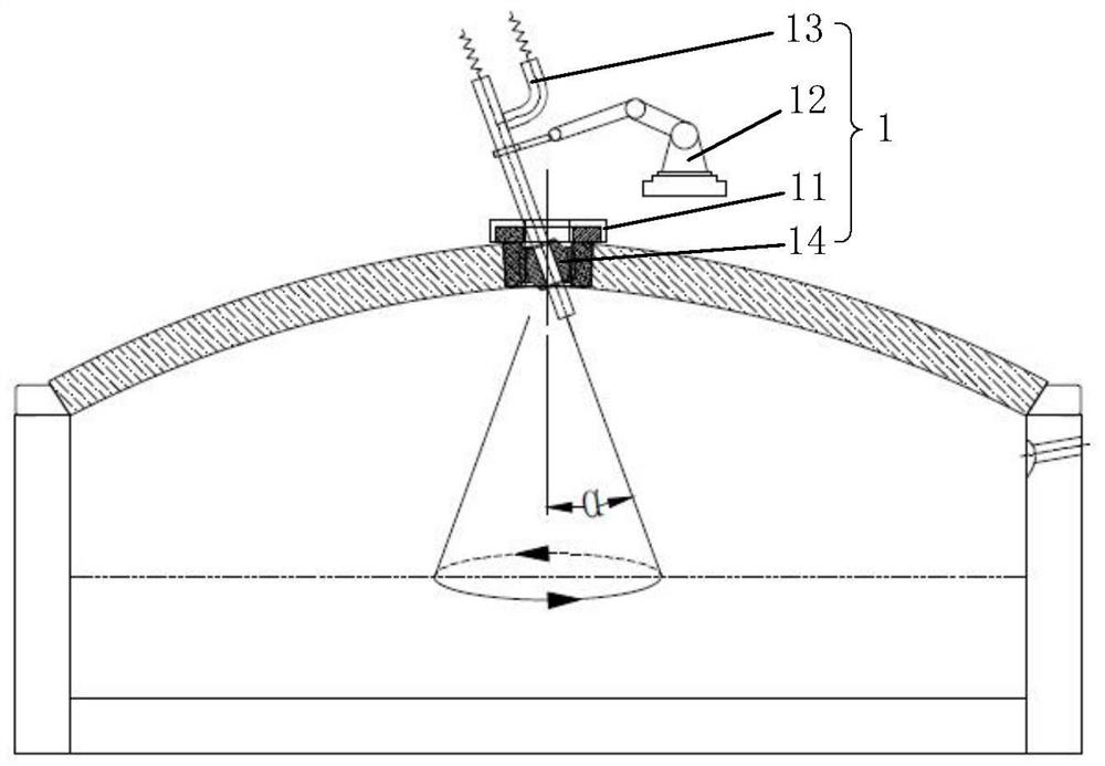
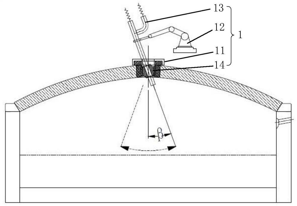
[0027] The present disclosure adopts a rotary combustion device to dynamically burn the materials in the kiln, and uses a multi-degree-of-freedom adjustment arm to rotate or swing the tubular burner. The action is fast and efficient, the adjustment range is large, and the top o...


PUM


Abstract

The present disclosure discloses a rotary combustion method for a kiln. The rotary combustion device installed on the top of the kiln includes a mounting base, an adjusting arm and a tubular burner, and the mounting base and the adjusting arm are both fixed on the top of the kiln, The middle part of the tubular burner is rotatably connected to the mounting base, and the output end of the tubular burner is located in the kiln; the output end of the adjusting arm is connected to the middle part of the tubular burner. The solution of the present disclosure uses the adjusting arm and the joint bearing to realize the rotation or swing adjustment of the tubular burner, realizes the dynamic heating of the materials in the kiln, and improves the overfire coverage area of ​​a single tubular burner; by controlling and adjusting the tubular burner The rotation period and rotation angle of the burner can carry out targeted and targeted combustion of refractory materials, agglomerates and run-off phenomena, effectively stabilizing the material line, ensuring the melting quality of the kiln, and greatly improving the melting rate of the kiln.

Description

technical field [0001] The present disclosure relates to the technical field of kiln combustion, and in particular, to a rotary combustion method of a kiln. Background technique [0002] In the process of molten glass melting, pure oxygen top-firing technology has been gradually promoted due to the advantages of complete combustion, high flame temperature, significant reduction of NOx emissions, stable process, energy saving, improving the quality of finished products and enhancing comprehensive benefits. application. Practice has shown that the structural arrangement of the combustion device is the core of the pure oxygen top-firing technology, and the reasonable arrangement of the combustion device can ensure that the flame can effectively cover the liquid glass surface, improve the melting quality of the molten glass, stabilize the material line, and reduce the leakage of material. [0003] In glass fiber production enterprises, they all pay more attention to the layout ...

Claims


Application Information

Patent Timeline
Patent Type & Authority Patents(China)
IPC IPC(8): C03B5/235F23L7/00F27B14/14
CPCC03B5/2353F23L7/007F27B14/143Y02E20/34Y02P40/50F23C5/06C03B5/235C03B5/24B25J9/1679B25J9/1697C03B2211/40
Inventor 曹国荣沈培军王海军方长应钱利根
Owner JUSHI GRP CO
Why Eureka
Try Eureka