Stainless steel bar heat treatment equipment

A technology for heat treatment equipment and stainless steel bars, applied in heat treatment equipment, heat treatment furnaces, furnaces, etc., can solve problems such as difficult processing of bars, and achieve the effects of reducing emissions, protecting the environment, and reducing use.

Active Publication Date: 2021-10-01
十堰高周波科工贸有限公司
View PDF6 Cites 1 Cited by
  • Summary
  • Abstract
  • Description
  • Claims
  • Application Information

AI Technical Summary

Problems solved by technology

[0004] The invention solves the problem that it is difficult to process bars with bent angles or ba

Method used


Image

  • Stainless steel bar heat treatment equipment
  • Stainless steel bar heat treatment equipment
  • Stainless steel bar heat treatment equipment

Examples


specific Embodiment approach

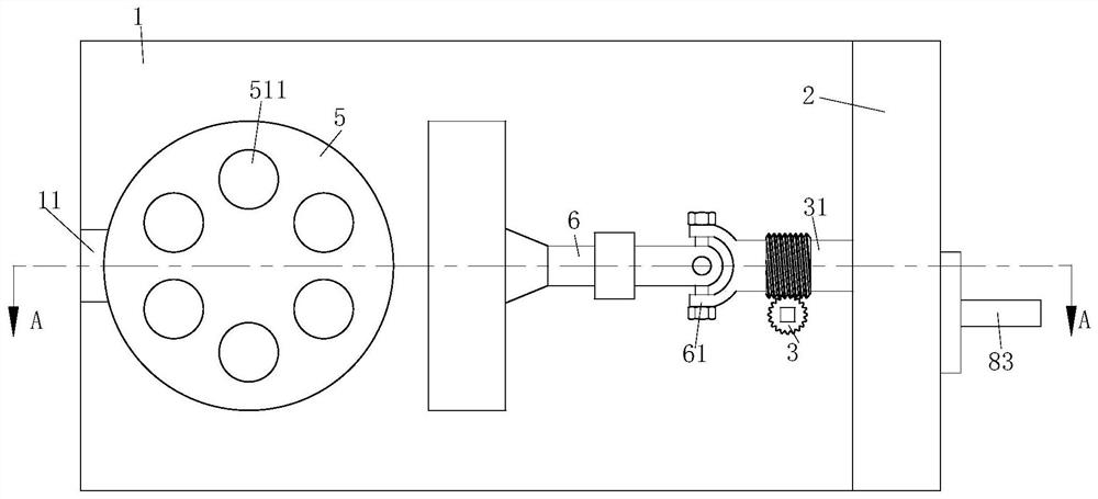
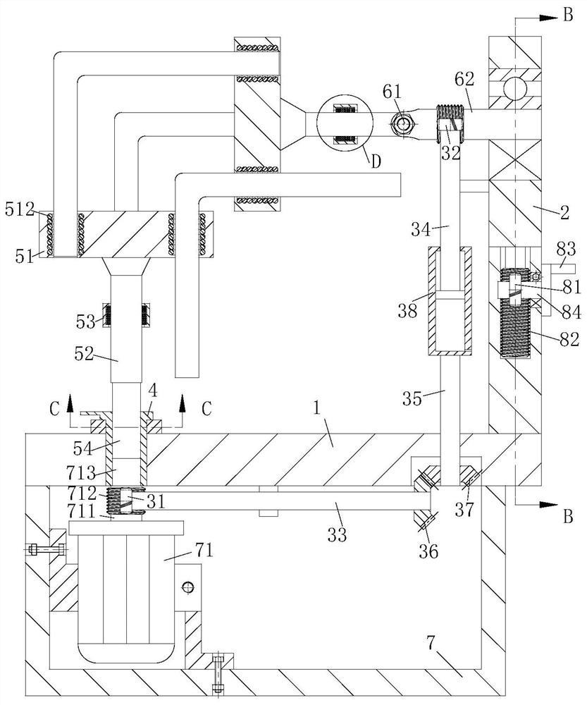
[0043] As a specific embodiment of the present invention, the brush plate 53 includes an inner ring 531 and an outer ring 532, the inner ring 531 is in interference fit with the connecting rod 52, and a plurality of copper rings are embedded in the inner ring 531 533, the copper ring 533 is electrically connected to the coil 512, the outer surface of the inner ring 531 is rotatably connected with an outer ring 532, and a plurality of copper sheets 534 are fixed on the side of the outer ring 532 close to the inner ring 531, a copper The sheet 534 is in contact with a copper ring 533, and the copper sheet 534 is electrically connected to an external power source. When the inner ring 531 and the outer ring 532 rotate relative to each other, the present invention contacts the copper ring 533 through the copper sheet 534 to realize the connection between the coil 512 and the outer ring 532. The external power source is always electrically connected.

[0044] As a specific embodimen...

Embodiment approach

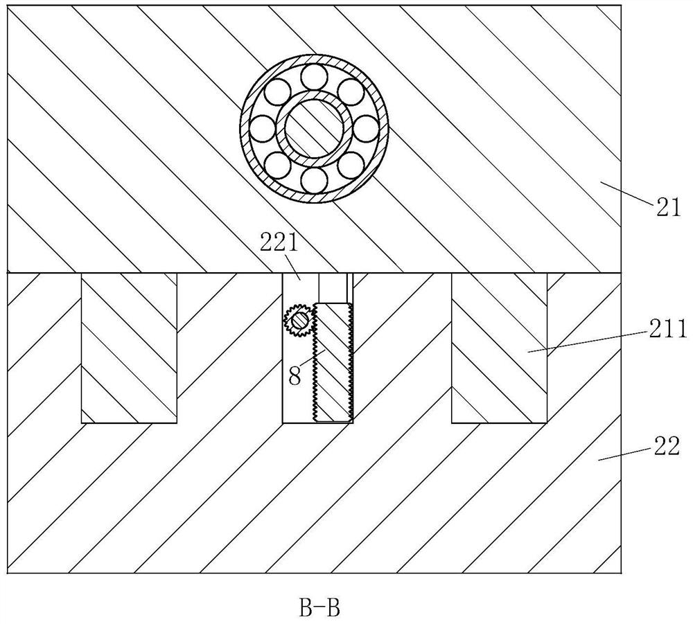
[0045] As a specific embodiment of the present invention, the side plate 2 includes a moving part 21 and a fixed part 22, the second rotating arm 6 is rotatably connected to the moving part 21, and the bottom end of the moving part 21 is fixed with a lift Mechanism 8 and a plurality of inserting blocks 211, the top of the fixed part 22 is provided with a plurality of slots 221, the lifting mechanism 8 and the inserting blocks 211 are arranged in the slots 221, the present invention drives the moving part 21 through the lifting mechanism 8 The insert block 211 at the bottom slides in the slot 221, thereby changing the height of the second rotating arm 6 on the moving part 21, and then cooperating with the universal coupling 61 on the second rotating arm 6 to change the height of the second rotating arm 6 The angle with the first rotating arm 5 realizes heat treatment of stainless steel rods with different bending angles.

[0046] As a specific embodiment of the present inventio...


PUM


Abstract

The invention relates to the technical field of heat treatment equipment, in particular to stainless steel bar heat treatment equipment. The equipment comprises a mounting plate, a first rotating arm and a second rotating arm, a groove is formed in one end of the mounting plate, the first rotating arm is rotationally connected into the groove, a side plate is fixed to the side, away from the groove, of the top end of the mounting plate, the second rotating arm is rotationally connected to the side plate, a motor box is fixed to the bottom end of the mounting plate, a motor is fixed to the side wall of the motor box through a fixing frame, an output shaft of the motor drives the first rotating arm to rotate through a connecting piece, spiral teeth are arranged on the outer surface of the output shaft, power is transmitted between the output shaft and the second rotating arm through a power transmission mechanism, and the power transmission mechanism is arranged in the motor box. The first rotating arm and the second rotating arm are driven by the motor to rotate, and heat treatment of a bent stainless steel bar is achieved in the rotating process of the first rotating arm and the second rotating arm which are specially designed.

Description

technical field [0001] The invention relates to the technical field of heat treatment equipment, in particular to a heat treatment equipment for stainless steel rods. Background technique [0002] Heat treatment refers to a metal thermal processing process in which materials are heated, kept warm and cooled in a solid state to obtain the desired structure and properties. [0003] A Chinese patent with application number 2017215171045 discloses a rolling-in type heat treatment device for stainless steel rods, including a box body, which is characterized in that a furnace door that is turned from top to bottom is provided on one side of the box body in the length direction , the furnace door is provided with side slide rails on both sides of the compartment; the compartment is provided with a support rail, and one end of the support rail towards the furnace door is hinged to the compartment and connected to the bottom end of the furnace door; The other end is provided with a ...

Claims


Application Information

Patent Timeline
IPC IPC(8): C21D9/08
CPCC21D9/08Y02P10/25
Inventor 李志鹏李建华
Owner 十堰高周波科工贸有限公司
Why Eureka
Try Eureka