

Vehicle cover guide rail connecting device
A technology of connecting device and guide rail, which is applied to the connection of rods, connecting members, and the suspension device of the wing fan, etc., can solve the problems of high transportation cost, collapse of the guide rail joint, easy damage, etc., and achieves good mechanical performance and installation accuracy. improved effect
- Summary
- Abstract
- Description
- Claims
- Application Information
AI Technical Summary
Problems solved by technology
Method used
Image

Examples
Embodiment 1
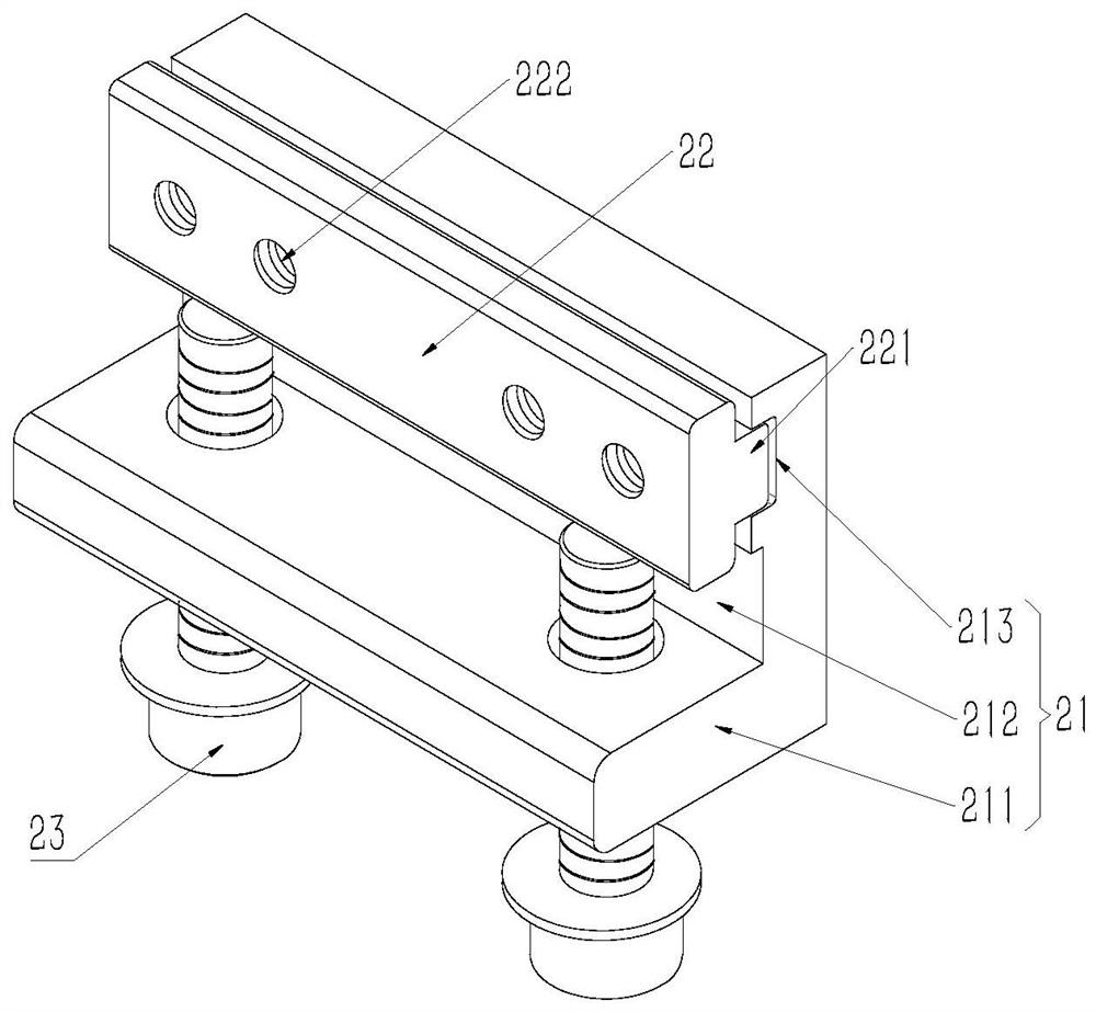
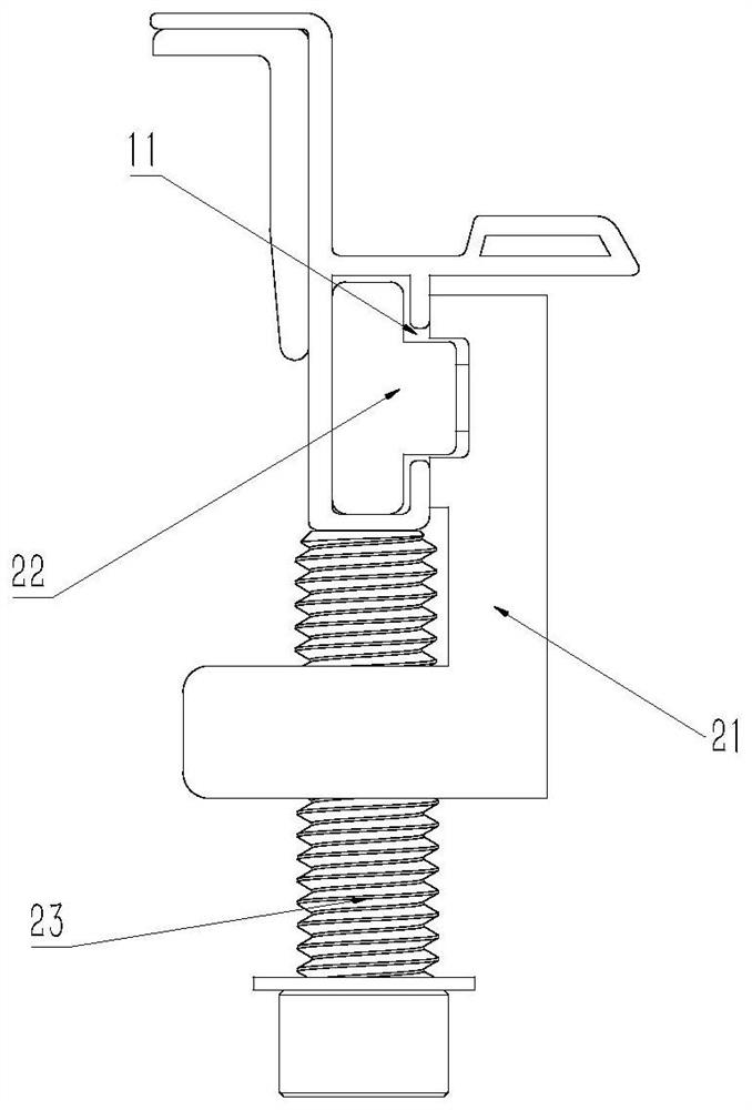
[0028] Such as figure 1 As shown, the vehicle cover rail connecting device includes a body 2, and the body 2 includes a first connecting block 21 and a second connecting block 22, the first connecting block 21 is arranged outside the guide rail 1, and the second connecting block 22 Extending into the inside of the guide rail 1 , the first connecting block 21 is connected to the second connecting block 22 , and the body 2 is connected with a supporting member for supporting the guide rail 1 .
[0029] The guide rail 1 is clamped and connected by the first connecting block 21 and the second connecting block 22, and then an upward prestress is applied to the guide rail 1 through the support to support the guide rail 1 and prevent the guide rail 1 from collapsing at the joint out of shape.
[0030] During use, first the second connecting block 22 is put into the inside of the guide rail 1 by the end of the guide rail 1, then the second connecting block 22 is positioned at the jun...
Embodiment 2
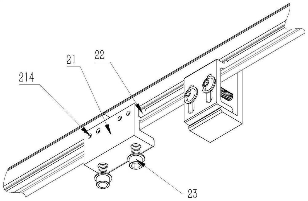
[0032] On the basis of Example 1, such as Figure 4 As shown, the first connecting block 21 and the second connecting block 22 are connected by connecting screws 24 .
[0033] The first connecting block 21 and the second connecting block 22 are connected by connecting screws 24, which not only facilitates disassembly, but also makes the first connecting block 21 and the second connecting block 22 more stable after being connected.
[0034] The supporting member is a pressure correction screw 23 .
[0035] The first connecting block 21 includes a supporting plate 211 and a connecting plate 212 , the connecting plate 212 is used for connecting with the second connecting block 22 , and the supporting plate 211 is used for connecting the compression correction screw 23 .
[0036] When connecting, screw the pressing and correcting screw 23 to the support plate 211 until the pressing and correcting screw 23 presses against the guide rail 1 .
Embodiment 3
[0038] On the basis of Embodiment 2, the supporting plate 211 and the connecting plate 212 are perpendicular to each other.
[0039] In actual use, the supporting plate 211 is arranged horizontally, and the connecting plate 212 is arranged vertically.
[0040] The first connecting block 21 adopts a structure of two plates, one of which is used to cooperate with the second connecting block 22 to clamp the guide rail 1 , and the other plate is used to connect the support to support the guide rail 1 .
[0041] The first connecting block 21 is an integral structure.
[0042] The first connecting block 21 is designed as an integrated structure, so that the first connecting block 21 has better overall stress performance.
PUM
 Abstract
Description
Claims
Application Information