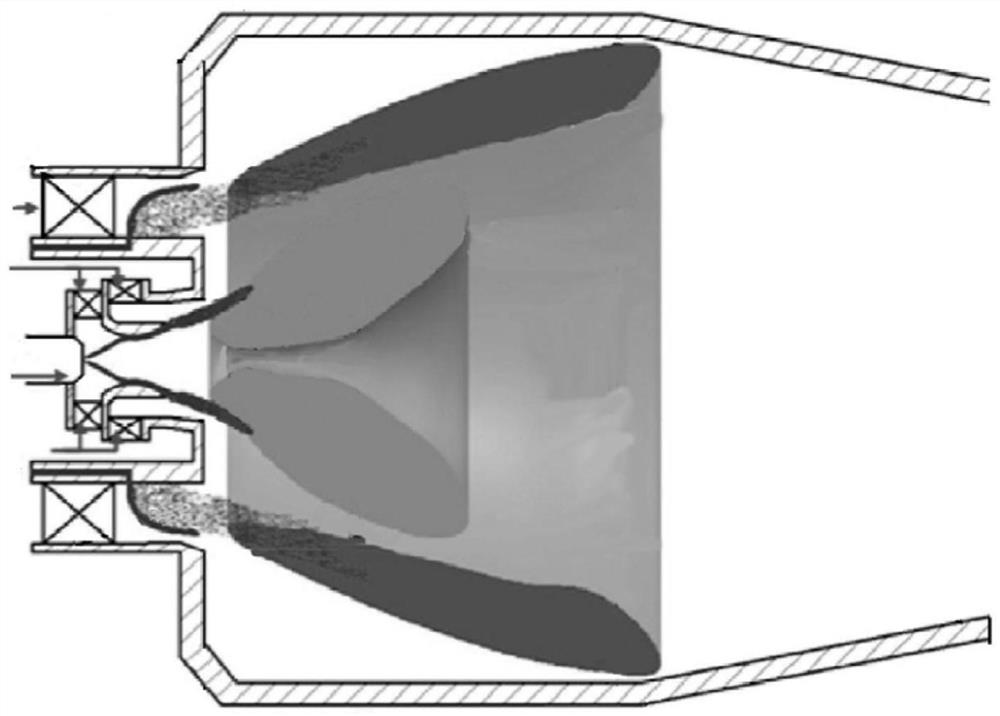
Center staged combustion chamber based on self-excitation sweeping oscillation fuel nozzles
A technology of fuel nozzles and central staging, which is applied in the field of aero-engine central staging combustion chambers, which can solve the problems of affecting fuel mixing, insufficient radial distribution uniformity, and complex pre-film injection structure, etc., and achieves miniaturized structural design and improved Effect of atomization performance and spatial distribution uniformity
- Summary
- Abstract
- Description
- Claims
- Application Information
AI Technical Summary
Problems solved by technology
Method used
Image

Examples
Embodiment Construction
[0033] The present invention will be further described in detail below in conjunction with the accompanying drawings and embodiments. It can be understood that the specific implementation manners described here are only used to explain relevant content, rather than to limit the present invention. In addition, it should be noted that, for the convenience of description, only the parts related to the present invention are shown in the drawings.
[0034] It should be noted that, in the case of no conflict, the embodiments and features in the embodiments of the present invention can be combined with each other. The present invention will be described in detail below with reference to the drawings and in combination with embodiments.
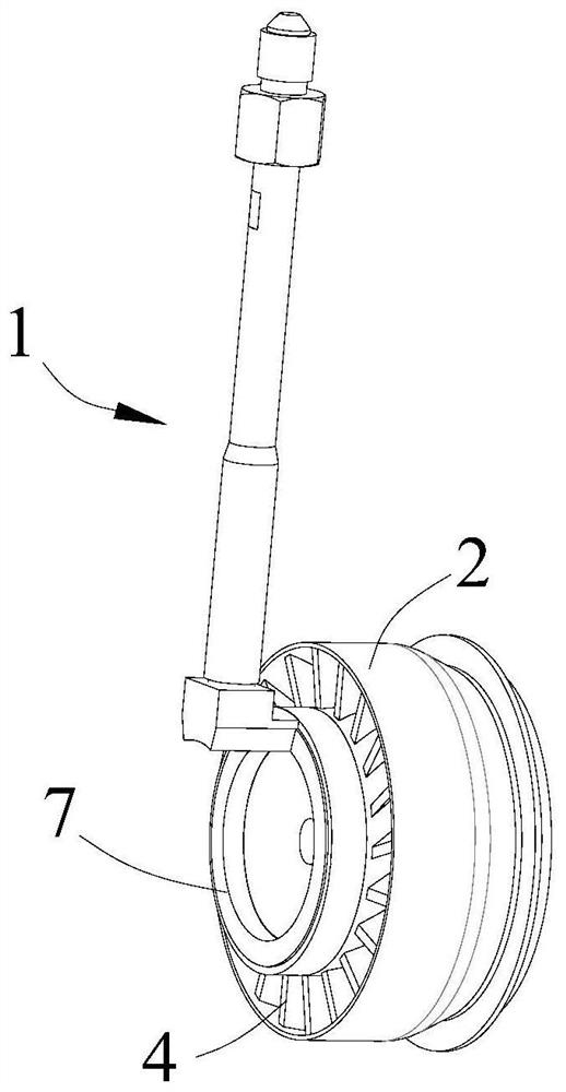
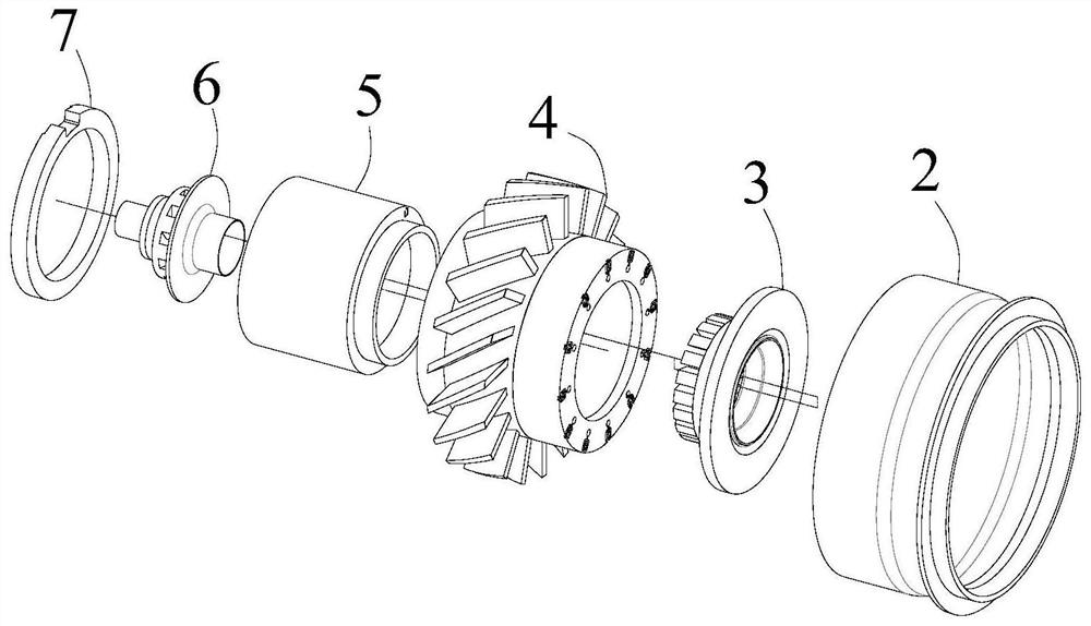
[0035] See attached Figure 2-3 , the present invention provides a center-staged combustor based on a self-excited sweep-oscillating fuel nozzle 45 . In terms of function, the central staged combustion chamber mainly includes oil delivery pipe 1, ou...
PUM
 Abstract
Description
Claims
Application Information