Check patentability & draft patents in minutes with Patsnap Eureka AI!

Laser micro frequency shift device and method based on column vector light field

A frequency offset and column vector technology, applied in the optical field, can solve the problems of poor performance, low output power, and excessive tunability, and achieve the effects of strong versatility, strong stability, and small overall volume.

Active Publication Date: 2021-10-01
XI AN JIAOTONG UNIV
View PDF5 Cites 0 Cited by
  • Summary
  • Abstract
  • Description
  • Claims
  • Application Information

AI Technical Summary

Problems solved by technology

In high-precision applications, the tunable frequency and output power of acousto-optic modulation and electro-optic modulation are difficult to meet the needs, and the broadening side effects of the adjustment method have gradually become one of the main parameters for evaluating the tuning method.
The tuning method with obvious spectrum broadening effect, too large tunable amount, and too small output power does not perform well in many fine-tuning scenarios

Method used


Image

  • Laser micro frequency shift device and method based on column vector light field
  • Laser micro frequency shift device and method based on column vector light field
  • Laser micro frequency shift device and method based on column vector light field

Examples


Embodiment Construction

[0044] The present invention is described in further detail below in conjunction with accompanying drawing:

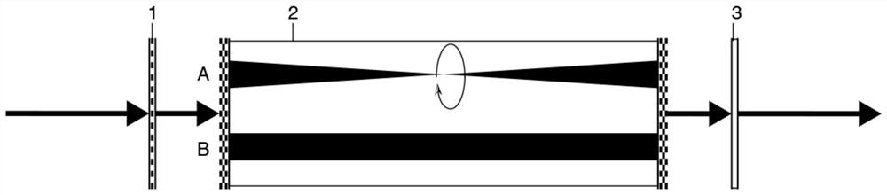
[0045] The working process of the optical instrument of the present invention is divided into three processes: generating cylindrical vector vortex light, polarization selective rotation, and reducing to fundamental mode Gaussian light. Performed with different polarization components of cylindrical vector vortex light in a polarization frame. Implemented as figure 1 As shown, it includes a conjugated helical phase polarizing polarizer 1, a polarization selective chirality inverter 2 and a non-polarizing helical phase plate 3. The collinear conjugated helical phase polarizing polarizer 1, the polarization selective chirality inverter 2 and the non-polarizing helical phase plate 3 are all cylinders, and the collinear conjugated helical phase polarizing polarizer 1, polarizing The selective chirality invertor 2 and the non-polarizing helical phase plate 3 are sequentia...


PUM


Abstract

The invention discloses a laser micro frequency shift device and method based on a column vector light field. The device comprises a conjugate spiral phase polarization polarizer, a polarization selective chiral reverser and a non-polarization spiral phase plate which are sequentially disposed in a light propagation direction, are collinear in axis, and are disposed at intervals or in a fit manner. The polarization selective chiral reverser comprises a first liquid crystal retarder, an anisotropic crystal and a second liquid crystal retarder which are sequentially connected in the light propagation direction; fast axes of the first liquid crystal retarder and the second liquid crystal retarder are uniformly arranged and respectively form included angles with the x axis, the X axis is vertical to the light propagation direction and is positioned on the horizontal plane; the length d of the anisotropic crystal along the light propagation direction is h which is the height of the anisotropic crystal vertical to the light propagation direction. The micro frequency offset device with a frequency micro offset function is realized.

Description

technical field [0001] The invention belongs to the field of optics, and relates to a laser micro-frequency shift device and method based on a cylindrical vector light field. Background technique [0002] Laser has excellent monochromaticity and coherence, and is a common light source in the fields of optical inspection and optical processing. Frequency is the basic parameter when laser is abstracted into a physical model, and it is indispensable in theoretical calculations related to laser. Accurate frequency can often greatly improve the calculation accuracy of various application scenarios and theories, so the precise adjustment and measurement of frequency has always been a key issue in the field of optics that needs to be improved urgently. [0003] The adjustment methods of laser frequency are roughly divided into two categories: intracavity and extracavity. Intra-cavity adjustment is to adjust the parameters of the resonant cavity in various ways, so that the unnece...

Claims


Application Information

Patent Timeline
Patent Type & Authority Applications(China)
IPC IPC(8): G02B26/00G02B27/28
CPCG02B26/002G02B27/286
Inventor 贾俊亮张沛赵子丹王晨辉
Owner XI AN JIAOTONG UNIV
Features
  • R&D
  • Intellectual Property
  • Life Sciences
  • Materials
  • Tech Scout
  • Unparalleled Data Quality
  • Higher Quality Content
  • 60% Fewer Hallucinations
Learn More