
Automatic evaluation method and system for visual positioning system

A visual positioning and positioning technology, applied in the field of computer vision, can solve the problems of inability to locate the device to obtain the true value, inconvenience to automatically evaluate the positioning quality, and relying on external equipment to obtain the true value of the positioning.

Inactive Publication Date: 2021-10-01
SHICHEN INFORMATION TECH SHANGHAI CO LTD
View PDF8 Cites 0 Cited by
  • Summary
  • Abstract
  • Description
  • Claims
  • Application Information

AI Technical Summary

Problems solved by technology

[0005] Embodiments of the present invention provide an automatic evaluation method and system for a visual positioning system to solve the problem that the acquisition of the true value of positioning in the prior art relies on external equipment, and the positioning device cannot be directly used to obtain the true value, which is not convenient for automatic evaluation of positioning quality. question

Method used


Image

  • Automatic evaluation method and system for visual positioning system
  • Automatic evaluation method and system for visual positioning system

Examples


Embodiment 1

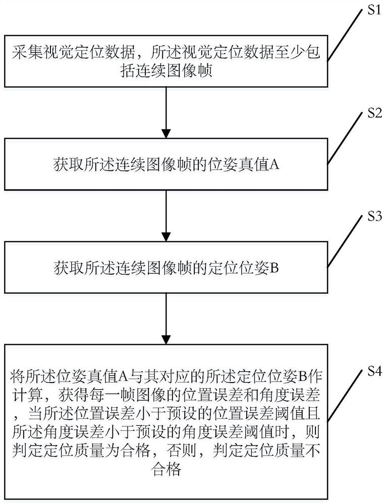
[0041] The first embodiment of the present invention will be described in detail below in conjunction with the accompanying drawings. like figure 1 A flow chart of an automatic evaluation method for a visual positioning system provided in the application is shown. Specifically include:

[0042] Step S1, collect visual positioning data. Specifically, a visual sensor can be mounted on the visual positioning system, such as a camera, which can be a monocular, binocular or multi-eye camera. Continuous frame images are taken for the positioning object, and the captured continuous frame images As visual positioning data, in some embodiments, the visual positioning system can also be equipped with inertial sensors, such as accelerometers, gyroscopes, magnetometers, GPS, etc., so that the inertial sensors and visual sensors can synchronously collect visual positioning data. In some embodiments, the visual positioning system refers to a visual positioning system used in technical fie...

Embodiment 2

[0058] The second embodiment of the present invention will be described in detail below in conjunction with the accompanying drawings. like figure 2 A schematic structural diagram of an automatic evaluation system for a visual positioning system provided in the application is shown. Specifically include:

[0059] The data acquisition module, specifically, can be a visual sensor carried in the visual positioning system, such as a camera, which can be a monocular, binocular or multi-eye camera, and takes continuous frame images for the positioning object, and uses the captured continuous frame images as a visual Positioning data. In some embodiments, the visual positioning system can also be equipped with inertial sensors, and the inertial sensors can be used as part of the data acquisition module, such as accelerometers, gyroscopes, magnetometers, GPS, etc., so that the inertial sensors can be collected synchronously with the visual sensors. Visual positioning data. In some...


PUM


Abstract

The embodiment of the invention provides an automatic evaluation method and system for a visual positioning system. In one method, the method includes obtaining consecutive image frames as visual localization data; obtaining a pose true value A of the continuous image frame; acquiring a positioning pose B of the continuous image frames; and calculating the pose truth value A and the positioning pose B corresponding to the pose truth value A to obtain a position error and an angle error of each frame of image, and when the position error is smaller than a preset position error threshold value and the angle error is smaller than a preset angle error threshold value, determining that the positioning quality is qualified, otherwise, determining that the positioning quality is unqualified. According to the method, the quality of the positioning result is completely and automatically evaluated, the result is reliable, the requirements for application scenes, operation modes and equipment are low, and manpower and material resources are saved.

Description

technical field [0001] The present application relates to the technical field of computer vision, in particular to an automatic evaluation method and system for a visual positioning system. Background technique [0002] Visual localization is to obtain the position and orientation of the image by matching the stable features in the image with the map. With the continuous development of camera technology, the camera's ability to perceive the world is getting stronger and stronger. There are more and more technologies that integrate 3D high-precision map capabilities, spatial computing capabilities, strong environmental understanding capabilities, and virtual-real fusion capabilities. In fields such as augmented reality, virtual reality, navigation, mobile robots, drones, and unmanned driving, obtaining the position and angle of the camera in space is a very important requirement. The conventional method is to do three-dimensional modeling of space or buildings, and make 3D m...

Claims


Application Information

Patent Timeline
IPC IPC(8): G06Q10/06G06T7/73
CPCG06Q10/06395G06T7/73
Inventor 顾升宇王强张小军
Owner SHICHEN INFORMATION TECH SHANGHAI CO LTD
Learn More