
Power system remote monitoring device and monitoring method thereof

A technology for remote monitoring devices and power systems, which is applied to circuit devices, substation/distribution device enclosures, and substation/switchgear cooling/ventilation. It can solve the problems of monitoring energy synchronization damage and avoid burning

Pending Publication Date: 2021-10-01
STATE GRID CORP OF CHINA +1
View PDF0 Cites 0 Cited by
  • Summary
  • Abstract
  • Description
  • Claims
  • Application Information

AI Technical Summary

Problems solved by technology

[0003] In addition, the power system monitoring in the prior art is mostly solved by pure electric control, but when the power system fails, the monitoring energy of pure electric control is often damaged synchronously. Therefore, a remote monitoring device for power system that reduces power control is proposed and It is particularly important to monitor

Method used


Image

  • Power system remote monitoring device and monitoring method thereof
  • Power system remote monitoring device and monitoring method thereof
  • Power system remote monitoring device and monitoring method thereof

Examples


Embodiment

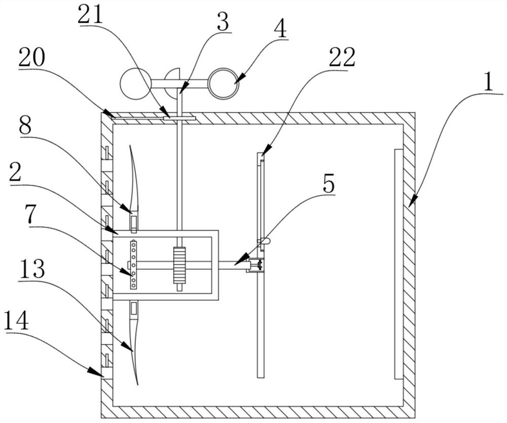
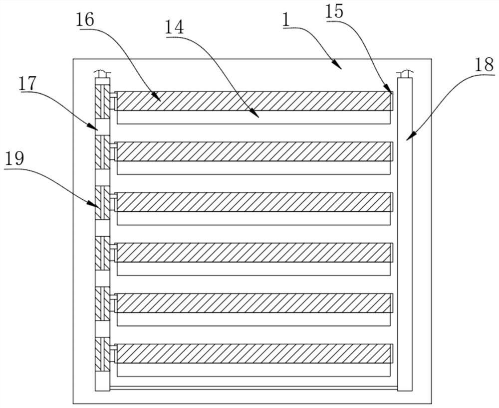
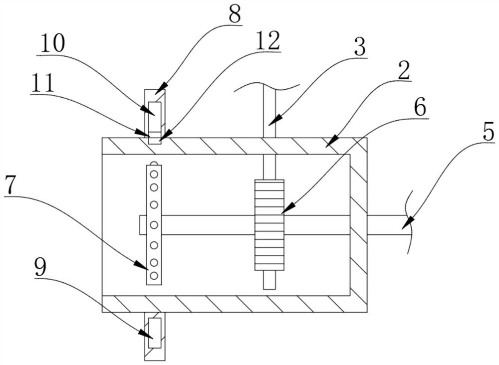
[0030] Refer Figure 1-5 A remote monitoring system of the power apparatus includes a monitor 24 and the power cabinet 1, monitor 24 includes an image capturing unit for capturing an image sequence, to generate the sensing signal of the sensor, the output unit and a processor the processor is electrically connected to the image capture unit, the output of the sensor unit; and a processor configured to upon receiving the sensing signal, the sensing signal determines whether the predetermined condition; and a processor configured to sense when the when the abnormality signal, is determined an event has occurred; and a processor configured to, when the event occurs, the number of occurrences within the first predetermined total time of the event, and within a second predetermined time captured by the image capturing unit of the image sequence for video; it occurs when the number of times equal to or greater than a predetermined number of times, the processor controls the output unit t...


PUM


Abstract

The invention discloses a power system remote monitoring device and a monitoring method thereof. The power system remote monitoring device comprises a monitor and a power cabinet. The monitor comprises an image acquisition unit used for acquiring an image sequence, a sensor used for generating a sensing signal, an output unit and a processor. The processor is electrically connected with the image acquisition unit, the sensor and the output unit; and a power cover is fixedly connected to the other side of the power cabinet, a power rod is rotatably connected to the upper wall of the power cover in a penetrating mode, and the upper end of the power rod upwards penetrates through the upper wall of the power cabinet and is fixedly connected with a wind cup. The device has the advantages that under the normal working condition, the wind cup rotates to drive the impeller to rotate so that a liquid in the right pipe is driven to flow upwards through the bottom of the left pipe, as the aperture of the through hole in the sliding column is small, the liquid moves upwards to push the sliding column to move upwards, and the liquid finally returns to the right pipe to form a loop; and the sliding column moves upwards to drive the baffle plate to move at a high position without blocking the air holes so as to ensure a high heat exchange speed inside and outside the power cabinet.

Description

Technical field [0001] The present invention relates to the field of power system monitoring technology, particularly to a remote monitoring device and the power system monitoring method. Background technique [0002] With the growing awareness to enhance the safety, security and surveillance applications are more and more attention. And now the power system as an indispensable part of daily life, the security of the power system is very important, but in the power system as a connecting node power cabinet power system, the probability of failure is higher than elsewhere. [0003] Also power system monitoring prior art is purely electronically controlled multi-way around, but the pure electric energy monitoring synchronous often damaged when the power system failure, for which proposes a power system remote monitoring device power control and reduction its method of monitoring is particularly important. Inventive content [0004] Object of the present invention is to solve the p...

Claims


Application Information

Patent Timeline
IPC IPC(8): H02J13/00H02B1/30H02B1/56H02B1/32
CPCH02J13/00022H02B1/30H02B1/565H02B1/32Y04S40/126Y02B90/20
Inventor 仝松利李玉杰张海霞
Owner STATE GRID CORP OF CHINA
Learn More