Automatic coiling mechanism of centerless lathe for titanium alloy wire production and coiling method
A technology of titanium alloy wire and centerless lathe, which is applied in the field of automatic coiling mechanism and coiling material of centerless lathe used in the production of titanium alloy wire, can solve the problems of sample processing accuracy and the influence of surface topography, and achieves the improvement of surface quality and vibration reduction. , the effect of reducing jitter
- Summary
- Abstract
- Description
- Claims
- Application Information
AI Technical Summary
Problems solved by technology
Method used
Image

Examples
Embodiment 1
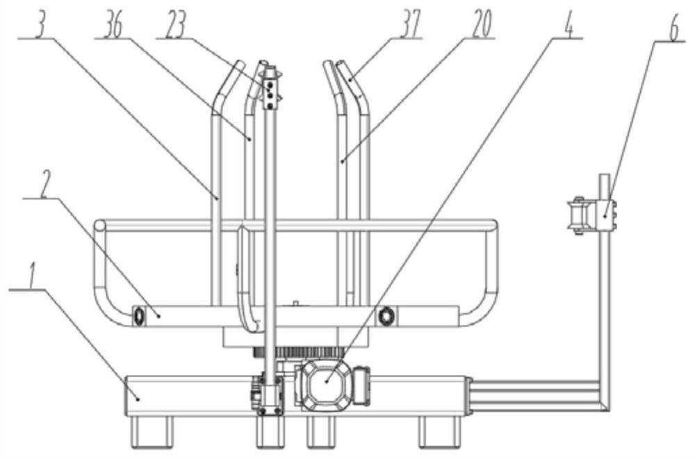
[0033] A kind of automatic coiling mechanism of centerless lathe for titanium alloy wire material production, such as figure 1 As shown, including coil material unit and coil size adjustment unit;
[0034] The coil size adjustment unit includes a base 1, a coil rack 2, a column assembly, a screw assembly, a coil adjustment motor 19, a coil adjustment shaft and a coil adjustment gear 15, and the coil rack 2 is installed on the top of the base 1, and the wire The rod assembly includes a leading screw and a leading screw gear connected with the leading screw. The column assembly is vertically installed on the inner bottom surface of the coil rack 2 through the leading screw assembly. The movement of the leading screw assembly drives the movement of the column assembly. At the upper center of the coil rack 2, one end of the coil adjustment shaft is connected with the coil adjustment motor 19, and the other end is connected with the coil adjustment gear 15; the coil adjustment gear...
Embodiment 2
[0037] Except for the following content, all the other contents are the same as in Example 1.
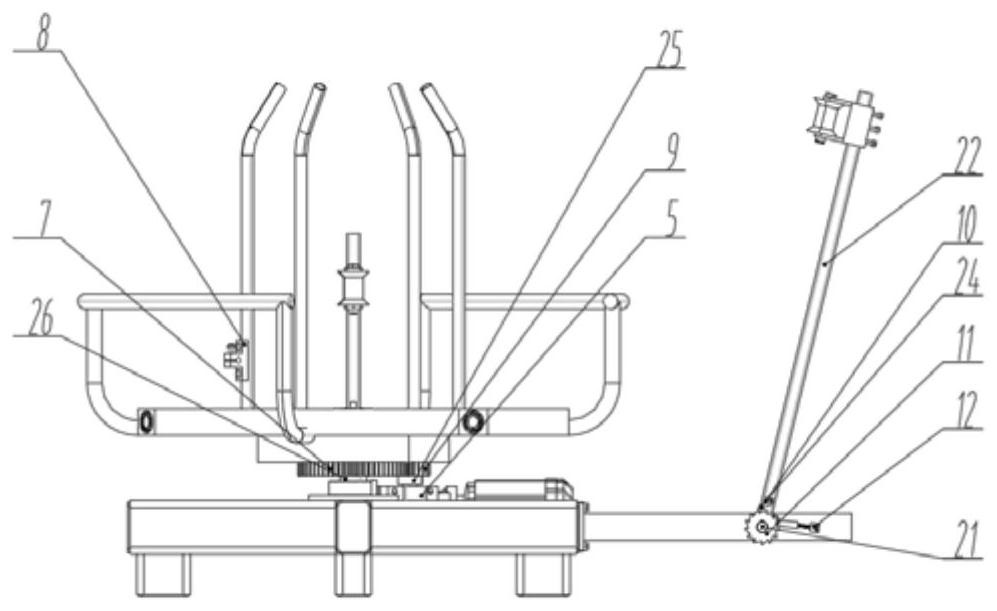
[0038]A ratchet frame 13 is installed on the first leg, and a ratchet shaft 21 is sheathed above the ratchet frame 13. One end of the ratchet shaft 21 is keyed to a ratchet 11, and the other end is vertically connected to a rocking bar 22. A ratchet frame is installed on the rocking bar 22. twenty four. One end of the rocking rod 22 is connected with the pawl frame 24, and the other end is connected with the first guide wheel 23 by bolts. A locker 12 for fixing the ratchet 11 is connected with bolts on the ratchet frame 13 . A guide frame 18 is installed on the second supporting leg, and the top of the guide frame 18 is connected with the second guide wheel 6 by bolts.
Embodiment 3
[0040] Except for the following content, all the other contents are the same as in Example 1.
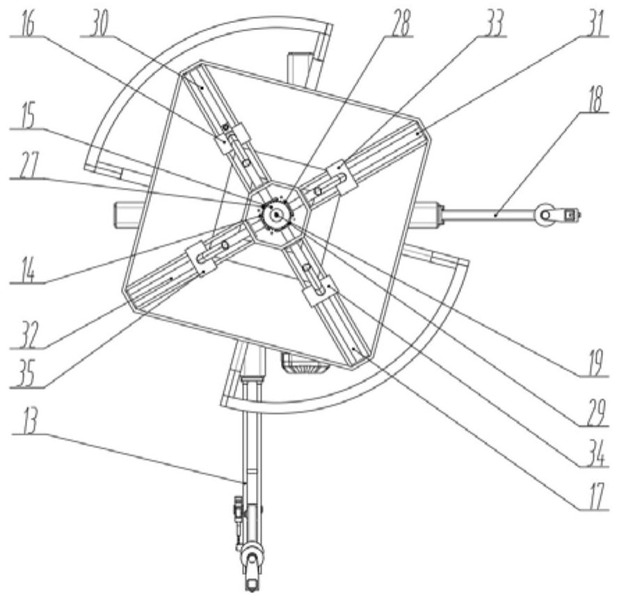
[0041] Such as image 3 As shown, the coil adjustment gear 15 meshes with the first lead screw gear 27 , the second lead screw gear 28 , the third lead screw gear 29 and the fourth lead screw gear 14 respectively. The first lead screw gear 27 is keyed to the first lead screw 30, the second lead screw gear 28 is keyed to the second lead screw 31, the third lead screw gear 29 is keyed to the third lead screw 17, and the fourth lead screw gear 14 is connected with the 4th leading screw 32 keys. The first leading screw 30, the second leading screw 31, the third leading screw 17 and the fourth leading screw 32 cooperate with the coil rack 2 through a leading screw bearing respectively, so that the first leading screw 30, the second leading screw 31, the second leading screw 32 The three leading screws 17 and the fourth leading screw 32 rotate on the fixed position of the coil rack 2 . ...
PUM
 Abstract
Description
Claims
Application Information
 - R&D
- Intellectual Property
- Life Sciences
- Materials
- Tech Scout
- Unparalleled Data Quality
- Higher Quality Content
- 60% Fewer Hallucinations
Browse by: Latest US Patents, China's latest patents, Technical Efficacy Thesaurus, Application Domain, Technology Topic, Popular Technical Reports.
© 2025 PatSnap. All rights reserved.Legal|Privacy policy|Modern Slavery Act Transparency Statement|Sitemap|About US| Contact US: help@patsnap.com