Optical lens, camera module and electronic equipment

An optical lens and lens technology, applied in the direction of optics, optical components, instruments, etc., to achieve the effect of reducing high-order aberrations, balancing chromatic aberrations, and shortening the total length

Active Publication Date: 2021-10-08
JIANGXI JINGCHAO OPTICAL CO LTD
View PDF13 Cites 2 Cited by
  • Summary
  • Abstract
  • Description
  • Claims
  • Application Information

AI Technical Summary

Problems solved by technology

At present, the market demand for the thinning of the existing optical lens and the design of the required aperture value is increasing, but how to increase the aperture value of the optical lens and shorten the length of the lens while maintaining good image quality is a huge challenge in the industry.

Method used


Image

  • Optical lens, camera module and electronic equipment
  • Optical lens, camera module and electronic equipment
  • Optical lens, camera module and electronic equipment

Examples


no. 1 example

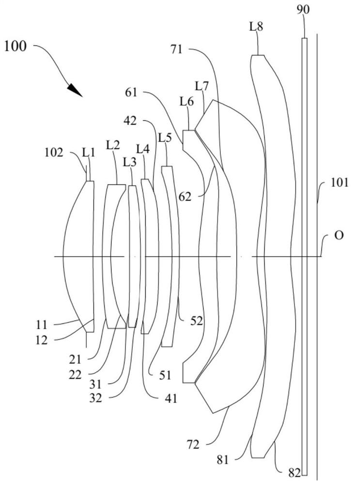
[0098] The structural diagram of the optical lens 100 disclosed in the first embodiment of the present application is as follows figure 1 As shown, the optical lens 100 includes a diaphragm 102, a first lens L1, a second lens L2, a third lens L3, a fourth lens L4, a fifth lens L5, a first lens L1, a fourth lens L4, a fifth lens L5, and a first lens L1 arranged sequentially from the object side to the image side along the optical axis O. Six lenses L6, seventh lens L7, eighth lens L8 and infrared filter 90.

[0099] Further, the first lens L1 has a positive refractive power, the second lens L2 has a negative refractive power, the third lens L3 has a positive refractive power, the fourth lens L4 has a positive refractive power, the fifth lens L5 has a negative refractive power, and the sixth lens L3 has a positive refractive power. Lens L6 has positive refractive power, seventh lens L7 has negative refractive power, and eighth lens L8 has negative refractive power.

[0100] Fur...

no. 2 example

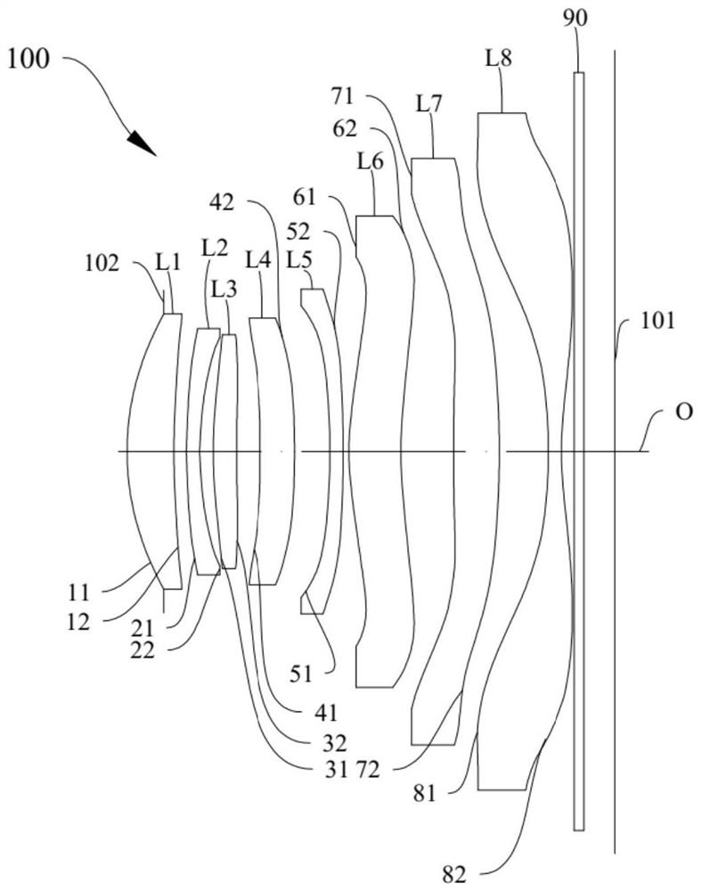
[0114] The structural diagram of the optical lens 100 disclosed in the second embodiment of the present application is as follows image 3 As shown, the optical lens 100 includes a diaphragm 102, a first lens L1, a second lens L2, a third lens L3, a fourth lens L4, a fifth lens L5, a first lens L1, a fourth lens L4, a fifth lens L5, and a first lens L1 arranged sequentially from the object side to the image side along the optical axis O. Six lenses L6, seventh lens L7, eighth lens L8 and infrared filter 90.

[0115] Further, the first lens L1 has a positive refractive power, the second lens L2 has a negative refractive power, the third lens L3 has a positive refractive power, the fourth lens L4 has a positive refractive power, the fifth lens L5 has a negative refractive power, and the sixth lens L3 has a positive refractive power. Lens L6 has positive refractive power, seventh lens L7 has positive refractive power, and eighth lens L8 has negative refractive power.

[0116] Fu...

no. 3 example

[0126] The structural diagram of the optical lens 100 disclosed in the third embodiment of the present application is as follows Figure 5 As shown, the optical lens 100 includes a diaphragm 102, a first lens L1, a second lens L2, a third lens L3, a fourth lens L4, a fifth lens L5, a first lens L1, a fourth lens L4, a fifth lens L5, and a first lens L1 arranged sequentially from the object side to the image side along the optical axis O. Six lenses L6, seventh lens L7, eighth lens L8 and infrared filter 90.

[0127] Further, the first lens L1 has a positive refractive power, the second lens L2 has a negative refractive power, the third lens L3 has a positive refractive power, the fourth lens L4 has a negative refractive power, the fifth lens L5 has a negative refractive power, and the sixth lens L3 has a negative refractive power. Lens L6 has positive refractive power, seventh lens L7 has positive refractive power, and eighth lens L8 has negative refractive power.

[0128] Fu...


PUM


Abstract

The invention discloses an optical lens, a camera module and electronic equipment. The optical lens comprises from an object side to an image side along an optical axis: a first lens, wherein the first lens has positive refractive power, and the object-side surface and the image-side surface of the first lens are convex and concave surfaces near the optical axis; a second lens with negative refractive power, wherein the second lens has an object-side surface and an image-side surface being convex and concave in a paraxial region thereof; a third lens with positive refractive power , wherein the third lens has an object-side surface being convex in a paraxial region thereof; a fourth lens which has an object-side surface being concave in a paraxial region thereof; a fifth lens with negative refractive power, wherein the fifth lens has an object-side surface and an image-side surface being concave and convex in a paraxial region thereof; a sixth lens with positive refractive power; a seventh lens, wherein the object side surface of the seventh lens is a convex surface at the optical axis; and an eighth lens with negative refractive power, wherein the eighth lens has an image-side surface being concave in a paraxial region thereof. The optical lens satisfies the following relational expression: f / EPD is more than or equal to 1.62 and less than or equal to 2.16. The optical lens, the camera module and the electronic equipment provided by the embodiment of the invention have the characteristics of large aperture and large image plane, and can realize high-quality imaging.

Description

technical field [0001] The invention relates to the technical field of optical imaging, in particular to an optical lens, a camera module and electronic equipment. Background technique [0002] With the development of science and technology, the specifications of electronic products are changing day by day, and the optical lenses among the key components are also more diversified. They not only pursue thinness and good imaging quality, but also pursue the design of large aperture and large image area. At present, there is an increasing market demand for the thinning of the existing optical lens and the design of the required aperture value. However, how to increase the aperture value of the optical lens and shorten the length of the lens while maintaining good imaging quality is a huge challenge in the industry. Contents of the invention [0003] The embodiment of the invention discloses an optical lens, a camera module and an electronic device, which can achieve miniaturi...

Claims


Application Information

Patent Timeline
Patent Type & Authority Applications(China)
IPC IPC(8): G02B13/00G02B13/18
CPCG02B13/0015G02B13/0045G03B30/00
Inventor 谭怡翔党绪文李明
Owner JIANGXI JINGCHAO OPTICAL CO LTD
Why Eureka
Try Eureka