Vehicle-mounted wireless charging equipment based on Internet of Vehicles and use method thereof

A vehicle-mounted wireless and charging equipment technology, which is applied to the structural components of electrical equipment, current collectors, electric vehicles, etc., can solve problems such as unknown wiring positions, heat dissipation, and inconvenient positioning and placement, and achieve improved charging stability and safety. The effect of improving stability

Pending Publication Date: 2021-10-08
史雯娟
View PDF1 Cites 0 Cited by
  • Summary
  • Abstract
  • Description
  • Claims
  • Application Information

AI Technical Summary

Problems solved by technology

[0004] The purpose of the present invention is to solve the shortcomings in the prior art, such as: 1. The wireless coil generates a lot of heat when charging, and the integrated charging device cannot dissipate the heat quickly, which affects the charging efficiency and top placement The battery life of the device; 2. It is inconvenient to locate and place, and it cannot be quickly assembled with the corresponding position of the vehicle, which affects the need for subsequent positioning and use; 3. The wiring position is unknown, and an additional opening is required at the assembly position, which affects the overall aesthetic effect. A vehicle-mounted wireless charging device based on Internet of Vehicles and its application method proposed

Method used


Image

  • Vehicle-mounted wireless charging equipment based on Internet of Vehicles and use method thereof
  • Vehicle-mounted wireless charging equipment based on Internet of Vehicles and use method thereof
  • Vehicle-mounted wireless charging equipment based on Internet of Vehicles and use method thereof

Examples


Embodiment approach

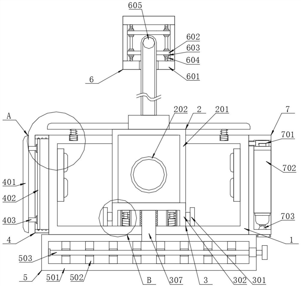
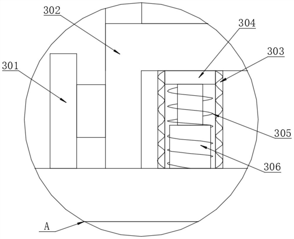
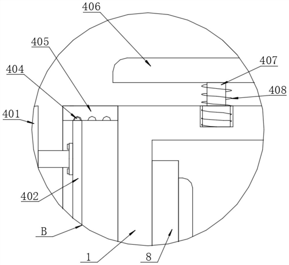
[0039] The specific embodiment is as follows: by placing the charging mechanism 2 and the externally connected placing base 1 into the upper storage slot reserved for the car storage box, the placing base 1 can pass through the first pressing plates 401 and 401 on both sides when it is snapped in. The second pressing plate 406 is squeezed and limited with the vehicle storage slot at the corresponding position. By placing the device to be charged into one side of the wireless charging plate body 201, it is placed vertically or horizontally with the wireless charging plate body 201 for contact charging. , when it is placed horizontally, the rubber pad in the inner cavity of the seat 1 can improve the stability of the snap-in. When it is placed vertically, it can be placed through the bottom fixing seat 302 to block and limit the position. When the charging device is placed, it can pass a magnetic The suction ring 202 is positioned quickly. When the wireless charging pad body 201 ...


PUM


Abstract

The invention discloses vehicle-mounted wireless charging equipment based on Internet of Vehicles and a use method thereof, and relates to the technical field of wireless charging. The vehicle-mounted wireless charging equipment comprises a placement base, wherein an inner cavity of the placement base is in transmission connection with a charging mechanism through a hinge mechanism, two sides of the inner cavity of the placement base are provided with limiting mechanisms, and the top part of the placement base is communicated with an air inlet mechanism. According to the vehicle-mounted wireless charging equipment, cold air generated in an air outlet of an armrest box is collected through an air inlet cover and guided into an air inlet pipe and a heat dissipation shell, the cold air entering the heat dissipation shell makes contact with heat absorption copper columns and heat dissipation fins for heat conduction, so that heat is rapidly absorbed, heat generated by the wireless charging panel body on the front side can be quickly absorbed and exchanged and then discharged into the air outlet cover through the air outlet pipe at the bottom, and the air outlet cover can discharge the heat from the bottom part of the storage box, so that the vehicle can be quickly cooled through circulating cold air, heat accumulation is prevented from influencing the charging efficiency and being guided into the battery cell of the intelligent equipment, and the charging stability and safety are improved.

Description

technical field [0001] The invention relates to the technical field of wireless charging, in particular to a vehicle-mounted wireless charging device based on the Internet of Vehicles and a method for using the same. Background technique [0002] The Internet of Vehicles is to realize the exchange of vehicle information and data through the Internet of Things chips. The important interactive terminals of the Internet of Vehicles are mobile smart surgical equipment or bracelet devices. With the development of science and technology, wireless charging has been able to achieve the needs of fast charging for smart devices. [0003] Chinese patent document CN108988501A discloses a wireless charging device for in-vehicle electronic equipment, comprising: a first tray for fixing the in-vehicle electronic equipment; a second tray is fixed on the car, and the orientation of the second tray is opposite to that of the first tray And the first tray can slide up and down on the inner sid...

Claims


Application Information

Patent Timeline
IPC IPC(8): H02J7/00H02J50/00H05K7/20H01R13/72
CPCH02J7/0042H02J50/00H05K7/2039H05K7/20145H01R13/72
Inventor 史雯娟
Owner 史雯娟
Why Eureka
Try Eureka