Waterproof power adapter with low loss and high heat dissipation

A power adapter, high heat dissipation technology, applied in the direction of electrical components, springs/shock absorbers, power electronics modification, etc., can solve the problems of power adapter short circuit, submersion into water, etc., to achieve the effect of improving the sealing effect

Inactive Publication Date: 2021-10-08
深圳市晋昂电子有限公司
0 Cites 1 Cited by

AI-Extracted Technical Summary

Problems solved by technology

[0003] In the existing technology, the power adapter generates heat during the working process, and the accumulation of heat in the power adapter will easily cause short circuit and other faults inside the p...

Abstract

The invention discloses a waterproof power adapter with low loss and high heat dissipation. The waterproof power adapter comprises a shell, wherein a heat dissipation opening is formed in the center of the right end face of the shell, a waterproof mechanism is arranged in the shell and the heat dissipation opening, the waterproof mechanism comprises waterproof grooves, a water-swelling rubber water-stop strip, an elastic groove, a water baffle, a ferromagnetic plate, a tension spring, a water stop groove, an electromagnet, a storage battery, a first metal sheet and a second metal sheet, a set of waterproof grooves are formed in each of the upper side and the lower side of the inner surface of the heat dissipation opening, and the storage battery powers on the electromagnet to enable the electromagnet to have magnetism. Therefore, the ferromagnetic plate is attracted to extend into the water stop groove, namely, the water baffle fixedly connected with the ferromagnetic plate extends into the water stop groove, when the water-swelling rubber water-stop strip expands, the water-swelling rubber water-stop strip can fill a gap, facing one side of the water-swelling rubber water-stop strip, of the water-stop plate after the water-swelling rubber water-stop strip extends into the water-stop groove, so that the sealing effect is further improved, the device has remarkable waterproofness, and the device is better protected.

Application Domain

Switch power arrangementsModifications for power electronics +3

Technology Topic

EngineeringMechanics +4

Image

  • Waterproof power adapter with low loss and high heat dissipation
  • Waterproof power adapter with low loss and high heat dissipation
  • Waterproof power adapter with low loss and high heat dissipation

Examples

  • Experimental program(1)

Example Embodiment

[0025] Next, the technical solutions in the embodiments of the present invention will be apparent from the embodiment of the present invention, and it is clearly described, and it is understood that the described embodiments are merely embodiments of the present invention, not all of the embodiments. Based on the embodiments of the present invention, there are all other embodiments obtained without making creative labor without making creative labor premises.
[0026] See Figure 1 to 3 The present invention provides a technical solution:
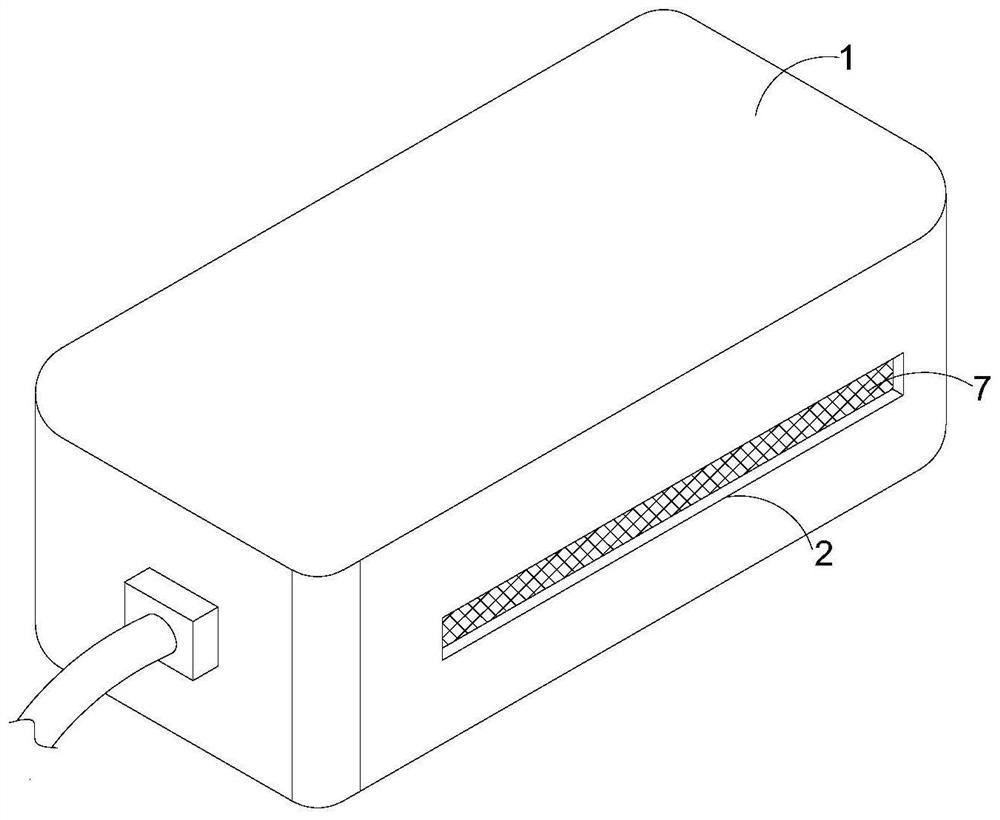
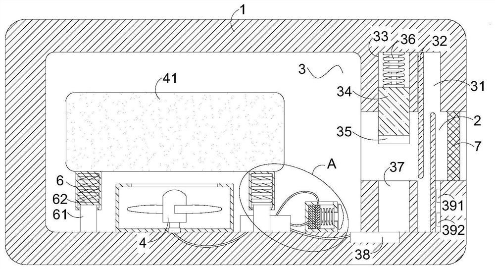
[0027] A waterproof power supply adapter having a low loss, including a housing 1, and a heat sink 2 is provided at the center of the housing 1, and the housing 1 and the heat dissipation port 2 are provided with waterproof mechanism 3;
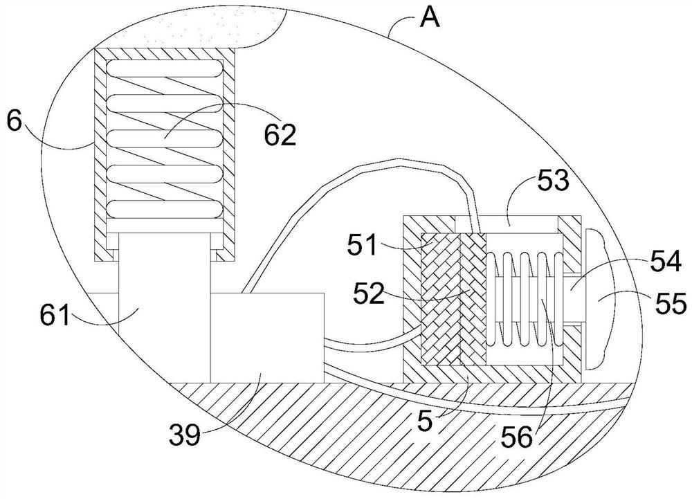
[0028] The waterproof mechanism 3 includes a waterproof groove 31, a water expansion rubber stopper strip 32, an elastic groove 33, a water retaining plate 34, a ferromagnetic plate 35, a tension spring 36, a water tank 37, an electromagnet 38, a battery 39, first The metal sheet 391, the second metal sheet 392, the upper side and the lower side of the inner surface of the heat sink 2 have a set of waterproof grooves 31, respectively, and each group is fixed to the bottom of the waterproof groove 31 fixed to the water expansion rubber stopper strip. 32, and each group is in contact with the water-expanded rubber stopper strip 32 side and the inner surface of the waterproof groove 31 in the surface of the waterproof groove 31, the surface of the waterproof groove 3 is disposed adjacent to the left side of the waterproof groove 33, and the elastic groove 33 is provided. The elastic groove 33 is opened on the upper side of the inner surface of the heat dissipation port 2, and the elastic groove 33 is passed through and slidably coupled, and the water retaining plate 34 is fixedly connected to a ferromagnetic plate 35, the water retaining plate 34. The upper end is fixed to the tensile spring 36, and the tension spring 36 is fixed to the upper end of the elastic groove 33 in the upper end of the elastic groove 33, and the elastic groove 33 is provided with a sink groove 37, and the sink 37 is opened at the bottom of the heat sink 2. The electromagnet 38 is attached to the bottom portion of the sink 37, and the electromagnet 38 and the battery 39 are connected by a wire, and the battery 39 is fixedly attached to the bottom bottom of the inner surface of the housing 1, and the electromagnet 38 other end passes through the wire. The first metal sheet 391 is fixed, and the first metal sheet 391 is fixedly attached to the right side of the waterproof groove 31 in the bottom of the heat dissipation port 2, and the first metal sheet 391 is adjacent to the second metal sheet 392, The second metal sheet 392 is fixed to the right side of the surface of the waterproof groove 31 opened at the bottom of the heat dissipation port 2 and does not contact the first metal piece 391, the second metal sheet 392 to securely attach to the battery 39 by a wire.
[0029] As an embodiment of the present invention, such as figure 2 As shown, the elastic groove 33 is fixedly coupled with a telescopic rod, and the lower end of the telescoping rod and the water retaining plate 34 are fixed, and the tension spring 36 is provided on the retractable rod.
[0030] When the device falls into the water due to the misoperation of the person, the waterproof mechanism 3 operates, and the water retaining plate 34 is moved down to extend into the water tank 37, the design of the retractable rod can limit the water retaining plate 34. Bits, the water retaining plate 34 can easily extend in the water tank 37 without the offset.
[0031] As an embodiment of the present invention, such as figure 1 with figure 2 As shown, a filter plate 7 is attached in the heathead port 2.
[0032] When working, the arrangement of the heat sink 2 inner filter plate 7 causes the external dust, solid particles, and the like to enter the housing 1 to reduce the probability of short-circuiting the electronic component in the power adapter main body 41 in the housing 1.
[0033] As an embodiment of the present invention, such as figure 2 Design, the battery 39 is coupled by a wire and a heat dissipation fan 4, and the heat dissipation fan 4 is fixedly coupled to the bottom of the housing 1, and a power adapter main body 41 is provided above the heat dissipation fan 4.
[0034]When operating, the battery 39 operates from the heat dissipation fan 4 to operate the heat dissipation fan 4, and the heat dissipation fan 4 operates to force the power adapter main body 41 in the housing 1 to force heat ventilation, wind and heat and flow through the heat sink 2, heat dissipation. When the fan 4 is forcibly dissipating ventilation, the wind and heat flow out of the heat sink 2 are outward axial winds to avoid dust into the housing 1 to further reduce dust in the power adapter main body 41 in the housing 1. The probability of short circuit of electronic components.
[0035] As an embodiment of the present invention, such as image 3 As shown, a control cartridge 5 is provided on the wire of the heat storage fan 4 connected to the heat dissipation fan 4, and the upper left end of the control cartridge 5 is fixedly coupled with a third metal sheet 51, and the third metal sheet 51 fixedly connected to the wire. Further, the third metal sheet 51 fixedly connected wire through the left end surface of the control cartridge 5 and fixed to the battery 39, the third metal sheet 51, the right end surface is bonded to the fourth metal sheet 52, the fourth metal sheet 52 In the control cartridge 5, the connection is slid, and the fourth metal sheet 52 is fixedly connected to the wire, and the wires upper end of the fourth metal sheet 52 penetrate through the rectangular groove 53 and the heat dissipation fan 4 is fixed, the rectangular groove 53 The upper end of the control cartridge 5 is opened, and the fourth metal sheet 52 is fixed to the upper side center, and the slider 54 is rotated through the right side of the right side of the control cartridge 5 and slides the connection, and the slider 54 extends. One end of the control cartridge 5 is fixed to the ferromagnetic block 55, and the slider 54 extends to one end sleeve of the control cartridge 5 is provided with a support spring 56.
[0036] When the device falls into the water due to human misoperation, the waterproof mechanism 3 operates, and the battery 39 supplies the electromagnet 38 to generate a magnetic pole attraction, and the electromagnet 38 sucks the ferromagnetic block 55 and causes the iron magnetic block. 55 moves horizontally toward the direction of the electromagnet 38, that is, the fourth metal sheet 52 fixed to the wire through the slider 54 is moved to the right level, thereby leaving the third metal sheet 51, at this time, the third metal sheet 51 and the first Since the four metal sheet 52 causes the battery 39 to supply the battery 39 to the heat dissipation fan 4, the heat dissipation fan 4 is stopped, thereby reducing energy loss.
[0037] As an embodiment of the present invention, such as figure 2 As shown, the lower end surface of the power source adapter body 41 separates the equal spacing with a set of support holes 6, and the lower end side wall of the support cartridge 6 is formed through the support rod 61 and slides, the support rod 61 penetrates into the support. 6 One end is fixedly connected to a damper spring 62, and the lower end of the support rod 61 is fixed to the bottom of the inner surface of the housing 1.
[0038] When operating, the device is inevitable when the device falls into the water in the process of falling into the water and the impairment of the device in the process of moving the device, and the device is inevitable, the support, the support rod 61 and the damper The interaction force between the spring 62 can buffer such vibration to protect the power adapter main body 41 in the housing 1.
[0039] Working principle: When the device is used, since the device falls into the water, the two groups in the waterproof groove 31 have a rapid expansion of the water expansion rubber stopper 32, and the two groups have a water expansion rubber stopper strip. 32 The rapid expansion of water absorbing is in contact with the phase together and sealed, thereby avoiding the water into the housing 1 to short the electronic components in the housing 1, and the waterproof groove 31 in the lower end of the surface of the heat dissipation port 2 is water expansion rubber stopper strip. 32 expansion and the first metal sheet 391, the second metal sheet 392, due to the characteristics of the water, the first metal sheet 391, the second metal sheet 392, and the water expansion rubber stopper strip 32 are in metallogenous rubber The water absorbed by the water strip 32 is connected, at which time the electromagnet 38, the battery 39, the first metal sheet 391, the second metal sheet 392, and several wires together form a closed path, at which time the battery 39 is energized to electromagnet 38 The iron 38 has magnetic properties to suck the ferrous plate 35 into the water tank 37, that is, the ferrule plate 34 fixed to the ferrous plate 35 extends into the water tank 37, and can be fill in the water expansion rubber stopper 32 expands. After returning the water retirement water tank 37, the gap between the water expansion rubber stopper strip 32 is met, thereby further improving the sealing effect such that the apparatus has significant waterproofability, thereby better protecting the device;
[0040] The battery 39 operates from the heat dissipation fan 4 to operate the heat dissipation fan 4, and the heat dissipation fan 4 is maintained to force the power adapter main body 41 in the housing 1 to force heat ventilation, the wind and heat, and flow through the heat sink 2, the heat dissipation port 2 The setting of the filter plate 7 causes the external dust, the solid particles, and the like, and when the heat dissipation fan 4 is forcibly dissipating, the wind and heat flow out of the heat sink 2, and the axial wind that can also avoid dust into the shell. In the body 1, the probability of short-circuiting the electronic component in the power adapter main body 41 in the housing 1 is reduced;
[0041] When the device falls into the water due to human misoperation, the waterproof mechanism 3 operates, and the battery 39 supplies the electromagnet 38 to generate a magnetic pole attraction, and the electromagnet 38 sucks the iron magnetic block 55 and causes the iron magnetic block 55 toward the iron magnetic block 55. The direction horizontal movement of the electromagnet 38, that is, the ferrous block 55 is moved to the right level by the fourth metal sheet 52 fixed to the slider 54, thereby leaving the third metal sheet 51, at which time the third metal sheet 51 and the fourth metal sheet 52 Since the battery 39 is difficult to supply the battery 39 to the heat dissipation fan 4, the heat dissipation fan 4 is stopped, thereby avoiding the inlet waterproof mechanism 3 to operate the housing 1 in the case, thereby reducing energy loss.
[0042] While the embodiments of the invention have been shown and described, these examples may be made to make a variety of changes, modifications, and replacement without departing from the principles and spirit of the present invention, without departing from the spirit and spirit of the present invention. And variations, the scope of the invention is defined by the appended claims and their equivalents.

PUM

no PUM

Description & Claims & Application Information

We can also present the details of the Description, Claims and Application information to help users get a comprehensive understanding of the technical details of the patent, such as background art, summary of invention, brief description of drawings, description of embodiments, and other original content. On the other hand, users can also determine the specific scope of protection of the technology through the list of claims; as well as understand the changes in the life cycle of the technology with the presentation of the patent timeline. Login to view more.

Similar technology patents

Bimetal joint

Owner:开封黄河空分集团有限公司

Medium-pressure high-performance rapid gas-liquid connector

Owner:青岛金谷子精密机械制品有限公司

Relay bottom sealing device

Owner:TAICANG SHINMEI ELECTRONIC CO LTD

Classification and recommendation of technical efficacy words

  • Improve the sealing effect

Water plugging device for petroleum pipeline maintenance

Owner:JIANGSU PROVINCE JINFENG PETROLEUM MACHINERY MFG CO LTD

Method for sintering polytetrafluoroethylene

Owner:广东新志密封技术有限公司

Brake pump piston ring of car air compressor

InactiveCN103790803AImprove the sealing effectreduce lower exhaust
Owner:NANJING FAYN PISTON RING

Annular sintering machine for water seal

ActiveCN103983111AImprove the sealing effectReduce air leakage
Owner:SHANDONG PROVINCE METALLURGICAL ENG CO LTD
Why Eureka
Try Eureka