Signal processing circuit, light receiving module and laser radar

A signal processing circuit and signal technology, applied in the field of signal processing, can solve the problems of affecting signal detection accuracy, clipping and saturation, etc., and achieve the effects of preventing oversaturation and broadening, stabilizing output, and adjusting magnification

Active Publication Date: 2021-10-08
LEISHEN INTELLIGENT SYST CO LTD
View PDF8 Cites 0 Cited by
  • Summary
  • Abstract
  • Description
  • Claims
  • Application Information

AI Technical Summary

Problems solved by technology

However, in the currently commonly used amplification circuits, when a small signal is input, that is, when the signal current is small, the signal can guarantee linear amplification, but when the signal becomes larger and larger, the amplitude of the signal will exceed the power supply after amplification. range, clipping and saturation occurs, and the signal is broadened, which will affect the subsequent detection accuracy of the signal, etc.

Method used


Image

  • Signal processing circuit, light receiving module and laser radar
  • Signal processing circuit, light receiving module and laser radar
  • Signal processing circuit, light receiving module and laser radar

Examples


Embodiment 1

[0040] figure 1 Shown is a schematic structural diagram of the signal processing circuit 10 of the embodiment of the present application.

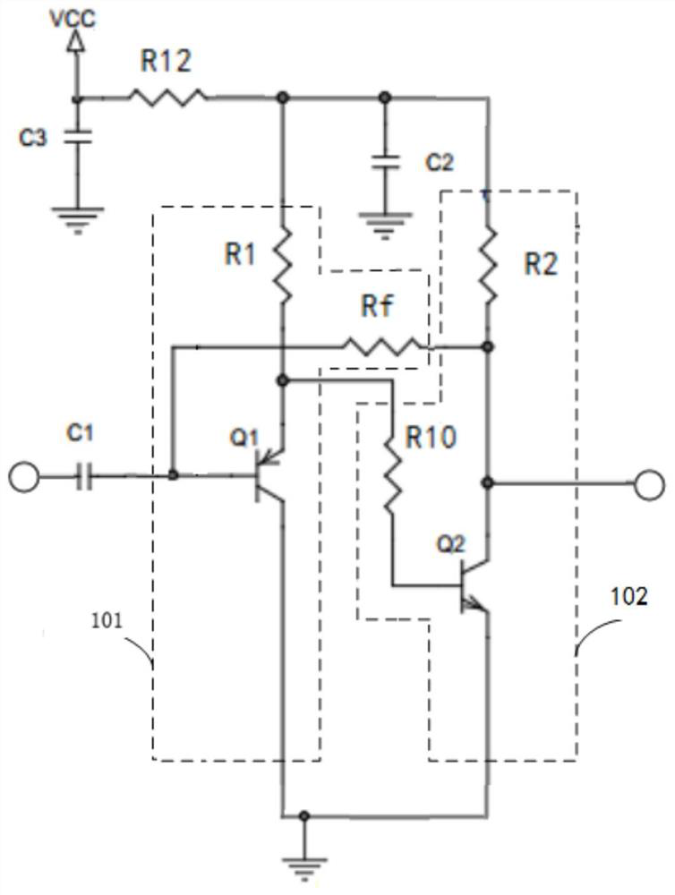
[0041]Exemplarily, the signal processing circuit 10 includes a signal conversion unit 101 and an active clamping unit 102, wherein the input terminal of the signal conversion unit 101 is used to access the current signal to be processed, and the output terminal of the signal conversion unit 101 is connected to the active clamp unit 102. The input end of the clamping unit 102 is electrically connected; the output end of the active clamping unit 102 is electrically connected to the feedback end of the signal conversion unit 101 .

[0042] The active clamp unit 102 is used to output the clamp voltage signal and feed back the clamp voltage signal to the input terminal of the signal conversion unit 101 through the feedback terminal of the signal conversion unit 101, so that the signal conversion unit 101 converts the input current signal is a ...

Embodiment 2

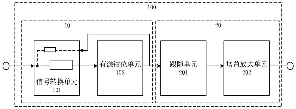
[0059] figure 2 Shown is a schematic structural diagram of the light receiving module 100 of this embodiment.

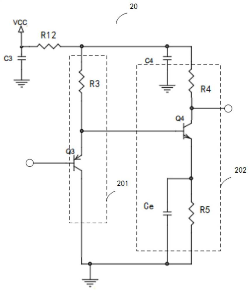
[0060] Exemplarily, the optical receiving module 100 includes a signal processing circuit 10 and a voltage amplifying circuit 20 electrically connected to the signal processing circuit 10, wherein the signal processing circuit 10 in the optical receiving module 100 can adopt the signal processing in the first embodiment above The circuit 10 is mainly used for signal conversion and clamping amplification to obtain a clamping voltage signal; the voltage amplifying circuit 20 is mainly used for gaining and amplifying the electrical output voltage signal processed by the signal processing circuit 10, so as to drive subsequent circuits, etc. .

[0061] In one embodiment, as figure 2 As shown, the signal processing circuit 10 includes a signal conversion unit 101 and an active clamping unit 102, wherein the output terminal of the signal conversion unit 101 is connected...


PUM


Abstract

The embodiment of the invention provides a signal processing circuit, an optical receiving module and a laser radar, the signal processing circuit comprises a signal conversion unit and an active clamping unit, the input end of the signal conversion unit is configured to input a current signal, the input end of the active clamping unit is electrically connected with the output end of the signal conversion unit, and the output end of the active clamping unit is electrically connected with the feedback end of the signal conversion unit; and the active clamping unit is used for feeding back an output clamping voltage signal to the input end of the signal conversion unit through the feedback end, so that the signal conversion unit converts a current signal into a voltage signal, and the active clamping unit is also used for carrying out clamping amplification on the voltage signal to obtain the clamping voltage signal. According to the technical scheme, the pulse width signal can be pre-amplified, meanwhile, the signal can be effectively prevented from being broadened, and the pulse width signal amplification circuit can be suitable for occasions with input signals with a wide change range.

Description

technical field [0001] The present application relates to the technical field of signal processing, in particular to a signal processing circuit, an optical receiving module and a laser radar. Background technique [0002] In some optical communication systems or audio systems, it is necessary to amplify the detected optical signal or sound signal. However, in the currently commonly used amplification circuits, when a small signal is input, that is, when the signal current is small, the signal can guarantee linear amplification, but when the signal becomes larger and larger, the amplitude of the signal will exceed the power supply after amplification. Range, clipping and saturation occurs, and the signal is broadened, which will affect the subsequent detection accuracy of the signal, etc. Contents of the invention [0003] Embodiments of the present application provide a signal processing circuit, an optical receiving module, and a laser radar. The signal processing circu...

Claims


Application Information

Patent Timeline
Patent Type & Authority Applications(China)
IPC IPC(8): H04B10/69G01S7/48G01S7/486
CPCH04B10/6932H04B10/691G01S7/48G01S7/486
Inventor 胡小波刘孙光
Owner LEISHEN INTELLIGENT SYST CO LTD
Why Eureka
Try Eureka