
Eureka
For R&D, Eureka makes reading and utilizing patents & technical documents easy.
Eureka AIR
Designed for self-driven R&D workflows. Generate viable solutions, solve complex R&D challenges, empower your innovation with AI.

Eureka Materials
Designed for material experts only. Revolutionize your material R&D, from search, analyze, to developing new materials.

TechResearch
Generate reliable direction feasibility study reports for your R&D in just a few steps.

TechSeek
Discover and master advanced knowledge NOW. Basics, ideas, possibilities, all at once.

TechMind
As an expert in R&D Theories, TechMind can generates customized viable solutions instantly.

TechRisk
Analyze your overall solution with one click, know your potential R&D risks in advance.

TechMonitor
Get weekly tech updates, stay abreast of the latest tech innovations and key insights.
Parameter setting assistance device, parameter setting assistance method, and parameter setting assistance program
An auxiliary device and parameter setting technology, applied in program control, instrumentation, adaptive control, etc., can solve problems such as complex control content and increased computing load
- Summary
- Abstract
- Description
- Claims
- Application Information
AI Technical Summary
Problems solved by technology
Method used
Image

Examples
Embodiment 1
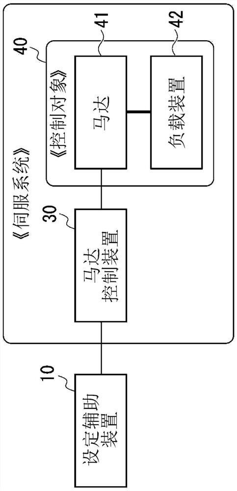
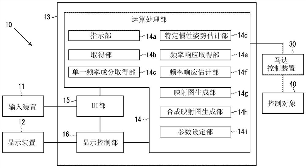
[0105] figure 1 A block diagram of the setting assistance device 10 of the present embodiment is shown. The setting assistance device 10 of this embodiment is a device for assisting the setting of control parameters in the motor control device 30 that controls a motor 41 that responds to a load whose mechanical parameters such as inertia change depending on the posture or situation. The device 42 is driven.
[0106]The motor control device 30 controls the motor 41 based on a command (position command, torque command, or speed command) input from a higher-level device (not shown) such as a PLC (Programmable Logic Controller: Programmable Logic Controller). Hereinafter, the portion constituted by the motor 41 and the load device 42 will be referred to as the controlled object 40 , and the portion constituted by the motor control device 30 and the controlled object 40 will be represented as the servo system.
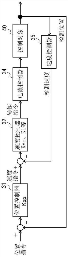
[0107] In the case of inputting a position command from a higher-lev...
Deformed example 1
[0160] In addition, in the above-mentioned embodiment, the reference posture is set to a posture different from the posture with the largest inertia value and the posture with the smallest inertia value, but in the above-mentioned embodiment, the posture with the smallest inertia value may be set as Baseline posture.
[0161] here, as Figure 13 As shown, the frequency response characteristic under the posture with the minimum inertia value (for example, as in embodiment 1) is to divide the value of each gain of the frequency response characteristic under the reference posture by the minimum ratio Jmin_ratio of the inertia value, so it can be considered that at the reference posture , the posture with the largest inertia value, and the posture with the smallest inertia value have the highest frequency response characteristics. Therefore, it can be considered that the reference posture is set to a posture different from the posture with the largest inertia value and the postur...
Deformed example 2
[0164] Next, Modification 2 of the present invention will be described. In the first embodiment described above, the frequency response characteristic is obtained at the reference posture, and the frequency response characteristic at the minimum inertia value posture is obtained by dividing this by the inertia value minimum ratio min_ratio. In addition, the frequency response characteristic in the inertia value maximum posture is obtained by dividing the frequency response characteristic in the reference posture by the inertia value maximum ratio max_ratio. On the other hand, in addition to the reference posture, the respective frequency response characteristics may also be measured for the minimum inertia value posture and the maximum inertia value posture.
[0165] Figure 16 The frequency response characteristics of the reference posture, the posture with the minimum inertia value, and the posture with the maximum inertia value in Modification 2 are shown. Estimated value...
PUM
 Abstract
Description
Claims
Application Information
 - R&D Engineer
- R&D Manager
- IP Professional
- Industry Leading Data Capabilities
- Powerful AI technology
- Patent DNA Extraction
Browse by: Latest US Patents, China's latest patents, Technical Efficacy Thesaurus, Application Domain, Technology Topic, Popular Technical Reports.
© 2024 PatSnap. All rights reserved.Legal|Privacy policy|Modern Slavery Act Transparency Statement|Sitemap|About US| Contact US: help@patsnap.com