A distributed generation power supply system and control method for at traction network
A technology of distributed power generation and power supply system, applied in power lines, vehicle components, transportation and packaging, etc., can solve problems such as waste and excessively long power lines, and achieve the goal of improving utilization rate, extending power supply distance, and improving the utilization of regenerative electric energy. Effect
- Summary
- Abstract
- Description
- Claims
- Application Information
AI Technical Summary
Problems solved by technology
Method used
Image

Examples
Embodiment 1
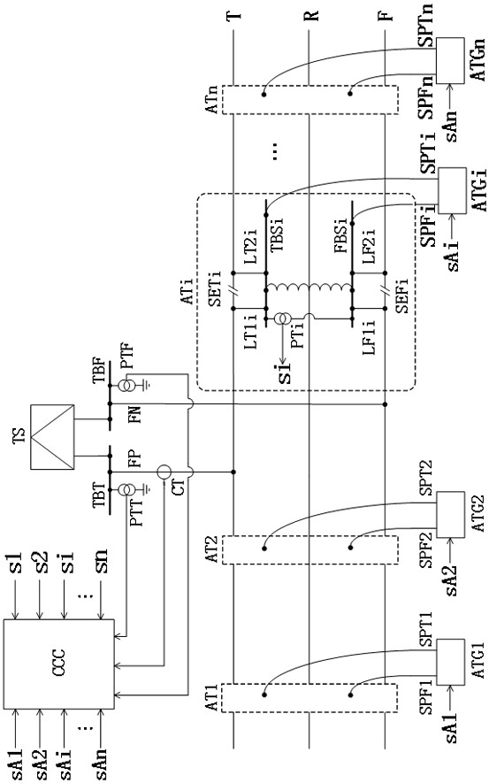
[0033] Such as figure 1 As shown, this embodiment provides an AT traction network distributed power supply system, including the AT traction network and the same-phase traction substation TS connected to the AT traction network, the traction bus TBT of the same-phase traction substation TS is connected to the The catenary T line of the AT traction network is connected, and the traction bus TBF of the traction substation TS of the same phase is connected with the catenary F line of the AT traction network through the feeder FN. The traction bus TBT is equipped with a voltage transformer PTT, and the traction bus TBF is set to the voltage The transformer PTF, the feeder FP is equipped with a current transformer CT, the AT traction network is equipped with an AT switching station, the neutral point of the AT switching station is connected to the rail R, and also includes a power generation device arranged along the railway direction, so The above-mentioned power generation device...
Embodiment 2
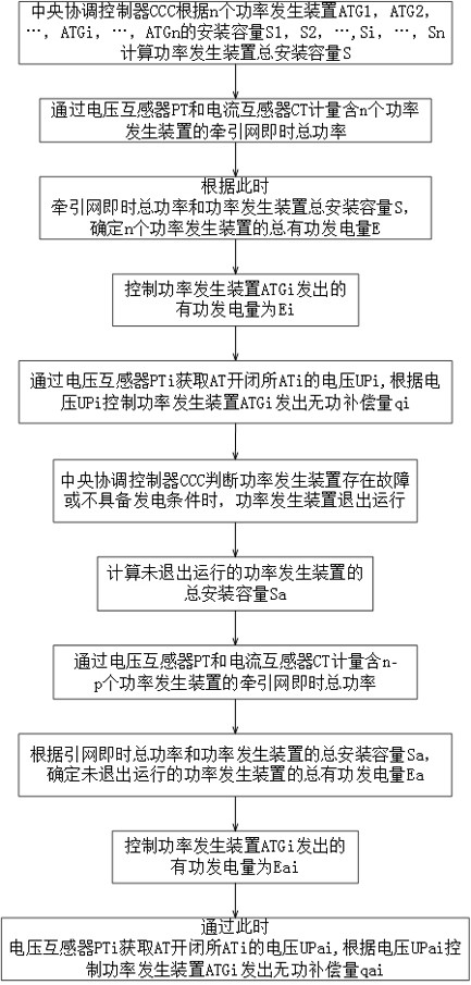
[0048] Such as image 3 As shown, this embodiment provides a control method based on the AT traction network distributed power supply system provided in Embodiment 1, which is applied to the central coordination controller CCC and realized through the following technical solutions:
[0049] The methods include:
[0050] The central coordinating controller CCC according to the installed capacities S1, S2, S1, S2, ..., Si, ..., Sn calculate the total installed capacity S of the power generating device, where, ;
[0051] The central coordinating controller CCC measures the real-time total power of the traction network with n power generating devices through the voltage transformer PT and the current transformer CT, and distinguishes the power consumption state and the power generation state;
[0052]Trains running on the line have three operating conditions: traction, regeneration and coasting. Traction is equivalent to electricity consumption, regeneration is equivalent to ...
PUM
 Abstract
Description
Claims
Application Information
 - R&D
- Intellectual Property
- Life Sciences
- Materials
- Tech Scout
- Unparalleled Data Quality
- Higher Quality Content
- 60% Fewer Hallucinations
Browse by: Latest US Patents, China's latest patents, Technical Efficacy Thesaurus, Application Domain, Technology Topic, Popular Technical Reports.
© 2025 PatSnap. All rights reserved.Legal|Privacy policy|Modern Slavery Act Transparency Statement|Sitemap|About US| Contact US: help@patsnap.com