

Optical glass
An optical glass and quality technology, applied in the field of optical glass, can solve the problems of easy deterioration of molds and unoptimized mold durability, and achieve the effects of high water resistance, low glass transition point, and improved stability.
Inactive Publication Date: 2021-10-12
NIHON YAMAMURA GLASS CO LTD
View PDF4 Cites 0 Cited by
- Summary
- Abstract
- Description
- Claims
- Application Information
AI Technical Summary
Problems solved by technology
[0007] In order to meet the above requirements, conventional glasses include LaK and LaF glasses, but most of them are glasses with a relatively high yield point, which causes the mold to deteriorate easily, and is not preferable for improving the durability of the mold.
Method used
View moreImage
Smart ImageViewing Examples

Examples
Embodiment
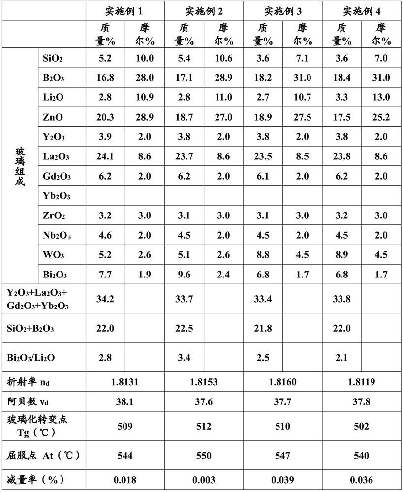
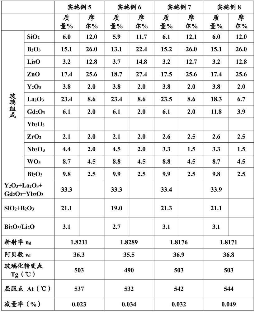
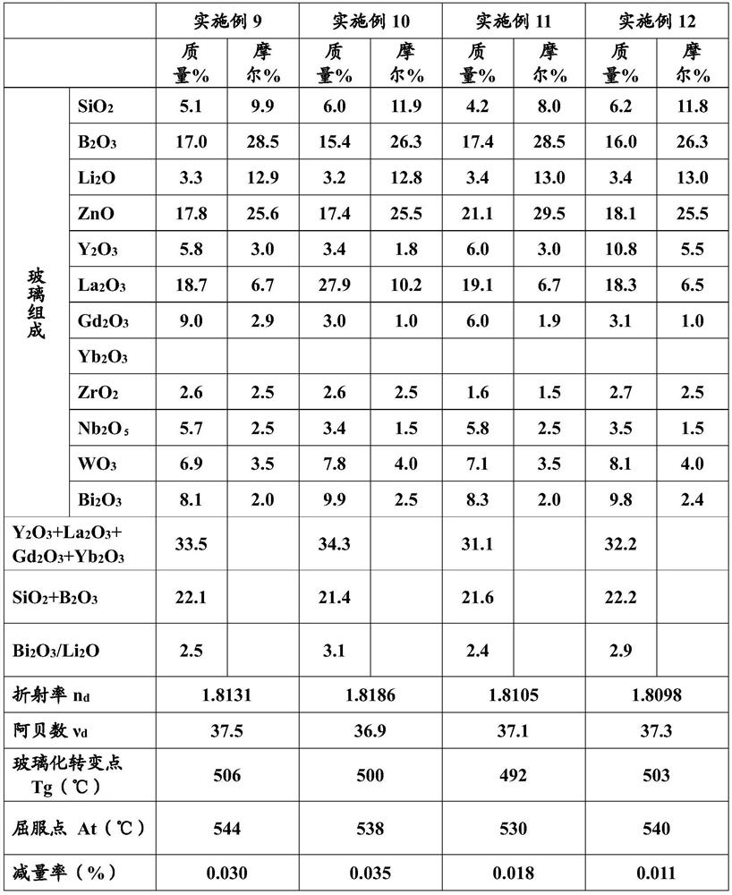
[0106] Hereinafter, the present invention will be further described with reference to examples. The present invention is not limited by these Examples.
[0107]The raw materials were prepared and mixed so as to have the composition of Examples 1 to 14 and Comparative Examples 1 to 4 shown in Tables 1 to 5, put into a platinum crucible, and melted in an electric furnace at 1200 to 1300° C. After clarification (degassing) and stirring, the temperature was lowered to 1000 to 1100° C., and then poured into a mold and slowly cooled to obtain optical glass.
Login to View More PUM
| Property | Measurement | Unit |
|---|---|---|
| glass transition temperature | aaaaa | aaaaa |
| glass transition temperature | aaaaa | aaaaa |
| length | aaaaa | aaaaa |
Abstract
The invention relates to optical glass. The present invention addresses the problem of providing optical glass having a high refractive index (particularly preferably 1.8 or more), a low dispersion (Abbe number being 35 or more), a low glass transition point (520 DEG C or less), a low yield point (550 DEG C or less), improved water resistance, and high glass stability, and being suitable for molding such as precision press molding and transfer of fine structures. The optical glass comprises 3.0 to 7.0 mass% of SiO2, 12.0 to 20.0 mass% of B2O3, 2.0 to 5.0 mass% of Li2O, 15.0 to 24.0 mass% of ZnO, 28.0 to 37.0 mass% of Y2O3, La2O3, Gd2O3 and Yb2O3, 16.0 to 29.0 mass% of La2O3, and 5.0 to 15.0 mass% of Bi2O3, and has a refractive index (nd) of 1.80 or more and a yield point (At) of 550 DEG C or less.
Description
technical field [0001] The present invention relates to optical glass, in particular to optical glass having a high refractive index, low dispersion and low yield point, and improved water resistance, having a composition suitable for molding and transfer of fine structures. Background technique [0002] In recent years, in the remarkable development of miniaturization and weight reduction of optical devices, aspheric lenses have been increasingly used. This is because the aspheric lens can easily correct ray aberration, reduce the number of lenses, and make the device compact. [0003] In addition, applications of optical glass other than aspheric lenses have also been developed, and it is desired to be able to accurately transfer the fine structure of the mold. [0004] Aspherical lenses and the like are produced by heating and softening a glass preform, and then precision press-molding it into a desired shape. There are roughly two methods of obtaining preforms, one is ...
Claims
Login to View More Application Information
Patent Timeline
 Patent Type & Authority Applications(China)
IPC IPC(8): C03C3/068C03C4/00
CPCC03C3/068C03C4/00
Inventor 日高达雄竹原辽太郎
Owner NIHON YAMAMURA GLASS CO LTD