Excess material recovery device for rotary kiln

A technology of recovery device and rotary kiln, applied in the field of rotary kiln, can solve the problems of structural damage of rotary kiln, poor thermal conductivity, influence of powder flow rate, etc., and achieve the effect of improving calcination efficiency and restoring thermal conductivity.

Pending Publication Date: 2021-10-12
安徽省泽乾冶金科技有限公司
View PDF0 Cites 0 Cited by
  • Summary
  • Abstract
  • Description
  • Claims
  • Application Information

AI Technical Summary

Problems solved by technology

[0002] Rotary kiln is widely used in the pre-sintering process of ferrite industry. For the pre-sintering process of ferrite powder, whether it is direct pre-sintering of powder, or pre-sintering of pellets or balls, the residual material sticks to the wall The phenomenon always exists objectively in different degrees. After the powder sticks to the wall in the rotary kiln, it not only affects the flow speed of the powder in the rotary kiln, but also reduces the thermal efficiency due to the poor thermal conductivity in the rotary kiln, resulting in This prevents a series of vicious cycle phenomena such as equipment output decline, poor consistency of powder pre-firing, unit energy consumption increase, and rotary kiln service life decrease.
[0003] In the prior art, steel balls or heavy hammer knocking devices are usually installed at the feed end of the rotary kiln, but the inventors found that this method easily leads to damage to the structure of the rotary kiln, and the phenomenon of residual material sticking to the wall remains Without a fundamental solution, the thermal conductivity of the rotary kiln is reduced, and the calcination efficiency of raw materials in the rotary kiln is seriously reduced

Method used


Image

  • Excess material recovery device for rotary kiln
  • Excess material recovery device for rotary kiln
  • Excess material recovery device for rotary kiln

Examples


Embodiment Construction

[0024] In order to make the purpose, technical solutions and advantages of the present disclosure clearer, the following in conjunction with specific examples, and refer to Figure 1-3 , to further describe the present disclosure in detail.

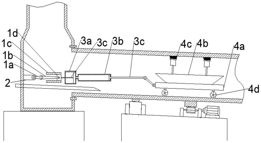
[0025] Based on the above purpose, one or more embodiments of this specification provide a rotary kiln residual material recovery device, characterized in that the residual material recovery device is arranged in the rotary kiln body, refer to figure 1 ,include:

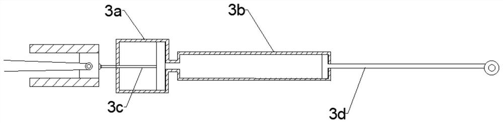
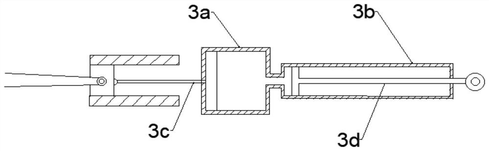
[0026] A reciprocating mechanism, one end of the reciprocating mechanism is rotatably connected to the fixture 2 arranged on the inner wall of the smoke exhaust chamber of the rotary kiln; the other end of the reciprocating mechanism is connected to a hydraulic distance increasing mechanism;

[0027] The recovery vehicle is connected with the hydraulic distance-increasing mechanism, and includes a vehicle body 4a and a recovery tank 4b fixed on the vehicle body 4a. A plurality ...


PUM


Abstract

One or more embodiments of the specification provide an excess material recovery device for a rotary kiln. The excess material recovery device is characterized in that the excess material recovery device is arranged in a rotary kiln body and comprises a recovery vehicle which is connected with a hydraulic distance increasing mechanism and comprises a vehicle body and a recovery tank fixed on the vehicle body; and a plurality of recovery brushes are arranged in the recovery tank, one ends of the recovery brushes are in frictional contact with the upper wall of a rotary kiln roller, and a plurality of rolling wheels which are in rolling contact with the lower wall of the rotary kiln roller are arranged at the bottom of the vehicle body. According to the excess material recovery device for the rotary kiln, the recovery brushes used for stripping the excess materials on the inner wall is arranged in the rotary kiln roller, the fallen excess materials are collected through the recovery tank, collection and recovery of the excess materials on the inner wall of the rotary kiln roller are achieved, the heat conductivity of the rotary kiln is recovered, and the calcination efficiency of raw materials in the rotary kiln is improved.

Description

technical field [0001] One or more embodiments of this specification relate to the field of rotary kiln technology, in particular to a rotary kiln residual material recovery device. Background technique [0002] Rotary kiln is widely used in the pre-sintering process of ferrite industry. For the pre-sintering process of ferrite powder, whether it is direct pre-sintering of powder, or pre-sintering of pellets or balls, the residual material sticks to the wall The phenomenon always exists objectively in different degrees. After the powder sticks to the wall in the rotary kiln, it not only affects the flow speed of the powder in the rotary kiln, but also reduces the thermal efficiency due to the poor thermal conductivity in the rotary kiln, resulting in This prevents a series of vicious cycle phenomena such as the decrease of equipment output, poor consistency of powder pre-firing, increase of unit energy consumption, and decrease of service life of rotary kiln. [0003] In th...

Claims


Application Information

Patent Timeline
IPC IPC(8): F27B7/20F27B7/26F27D25/00
CPCF27B7/2075F27B7/26F27D25/001
Inventor 艾世勇汪茂荣
Owner 安徽省泽乾冶金科技有限公司
Why Eureka
Try Eureka