Valve prosthesis and valve prosthesis system

A valvular prosthesis and valve technology, applied in the field of valvular prosthesis and valvular prosthesis system, can solve problems such as fracture, obstruction of stent rod compression, large strain, etc.

Pending Publication Date: 2021-10-15
SHANGHAI YIQIAO MEDICAL EQUIP CO LTD
View PDF0 Cites 3 Cited by
  • Summary
  • Abstract
  • Description
  • Claims
  • Application Information

AI Technical Summary

Problems solved by technology

In the process of crimping, the fixed connection point at the upper end will restrict the support rod, hindering the crimping of the support rod.
In addition, after the crimping is completed, the upper end of the support

Method used


Image

  • Valve prosthesis and valve prosthesis system
  • Valve prosthesis and valve prosthesis system
  • Valve prosthesis and valve prosthesis system

Examples


Embodiment Construction

[0049] Embodiments of the present invention will be described in detail below, and the embodiments described with reference to the accompanying drawings are exemplary.

[0050] Refer below Figure 1-Figure 14 The valve prosthesis 100 according to the embodiment of the present invention is described, and the present invention also proposes a valve prosthesis system having the above valve prosthesis 100 .

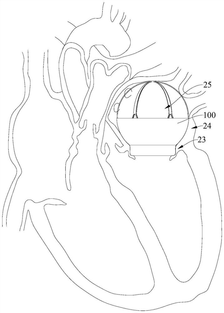
[0051]The valve prosthesis 100 of the present invention can be used to replace native valve structures such as mitral valve, tricuspid valve, aortic valve and pulmonary valve, and the replacement of mitral valve is used as an example below.

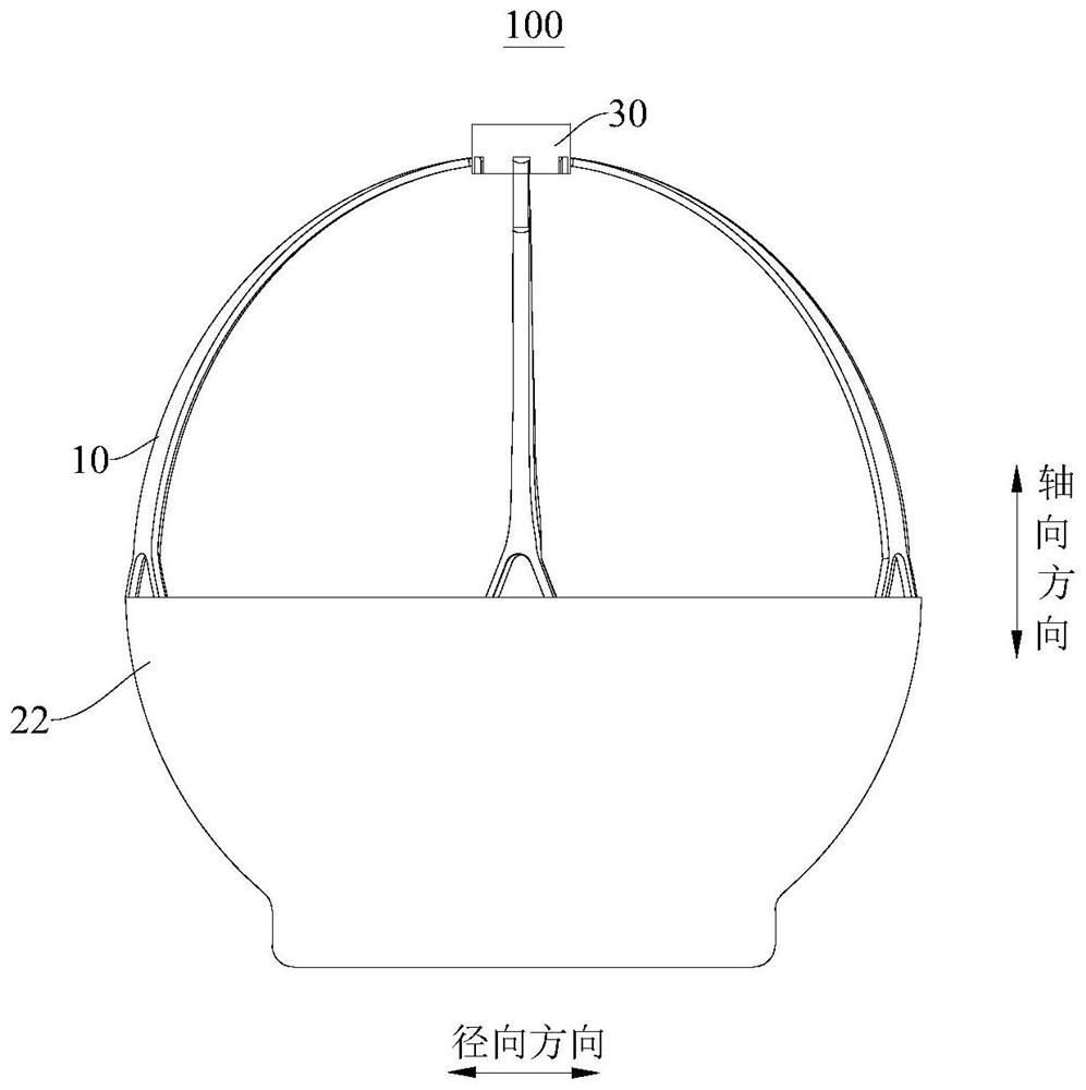
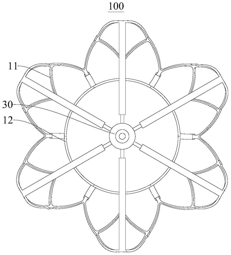
[0052] Such as Figure 1-Figure 5 As shown, the valve prosthesis 100 according to the embodiment of the first aspect of the present invention comprises: valve support 10, leaflets, skirt 22 and connector 30, valve support 10 comprises: outer support 11 and inner support 12, outer support 11 and The inner stent 12 is connected and locat...


PUM


Abstract

The invention discloses a valve prosthesis and a valve prosthesis system. The valve prosthesis comprises a valve stent, the valve stent comprises an outer stent and an inner stent, the outer stent and the inner stent are connected and located on the periphery of the inner stent, the outer stent comprises: an atrium matching part, wherein the atrium matching part comprises a plurality of first support rods, the plurality of first support rods are distributed in the circumferential direction and connected in sequence, and each first support rod is provided with a movable end; a valve leaflet which is fixed on the inner stent; a skirt edge which covers the inner surface and/or the outer surface of the valve stent; connectors which are arranged at the movable ends of the first support rods and allow the first support rods to move between the contraction position and the expansion position. The connectors are arranged at the movable ends of the first support rods, so that the first support rods can move between the contraction positions and the expansion positions, and the first support rods can be smoothly expanded or contracted.

Description

technical field [0001] The invention relates to the technical field of medical instruments, in particular to a valve prosthesis and a valve prosthesis system. Background technique [0002] The mitral valve is a valve in the heart that separates the left atrium from the left ventricle. The mitral valve acts as a "one-way valve" that allows blood to flow in one direction by opening or closing. Under normal circumstances, the mitral valve allows blood to flow from the left atrium to the left ventricle, but if the mitral valve is incompetent, when the heart contracts, part of the blood flow will return to the left atrium, which is "mitral regurgitation". Mitral regurgitation increases the load on the heart, lungs, and other organs. In some patients, the heart must contract and relax harder to pump blood throughout the body, resulting in an enlarged heart. As the condition gradually worsens, other more serious heart problems (such as global heart failure) will eventually appear...

Claims


Application Information

Patent Timeline
IPC IPC(8): A61F2/24
CPCA61F2/2418A61F2/2424A61F2/2436A61F2/2439
Inventor 王广卉黎鹏谢建
Owner SHANGHAI YIQIAO MEDICAL EQUIP CO LTD
Why Eureka
Try Eureka