Coal mine fully-mechanized excavating machine onboard dust extraction and purification device
A purification device and fully mechanized excavator technology, which is applied in mining devices, safety devices, dust prevention, etc., can solve the problems of noise pollution, large size of dust collector, and inability to fundamentally improve the working environment, and achieve the effect of ensuring air volume
- Summary
- Abstract
- Description
- Claims
- Application Information
AI Technical Summary
Problems solved by technology
Method used
Image

Examples
Embodiment Construction
[0017] In order to make the object, technical solution and advantages of the present invention more clear, the present invention will be further described in detail below in conjunction with the examples. It should be understood that the specific embodiments described here are only used to explain the present invention, and are not intended to limit the present invention, that is, the described embodiments are only some of the embodiments of the present invention, but not all of the embodiments.
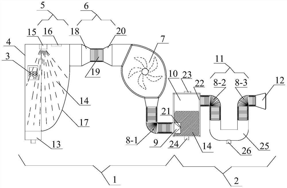
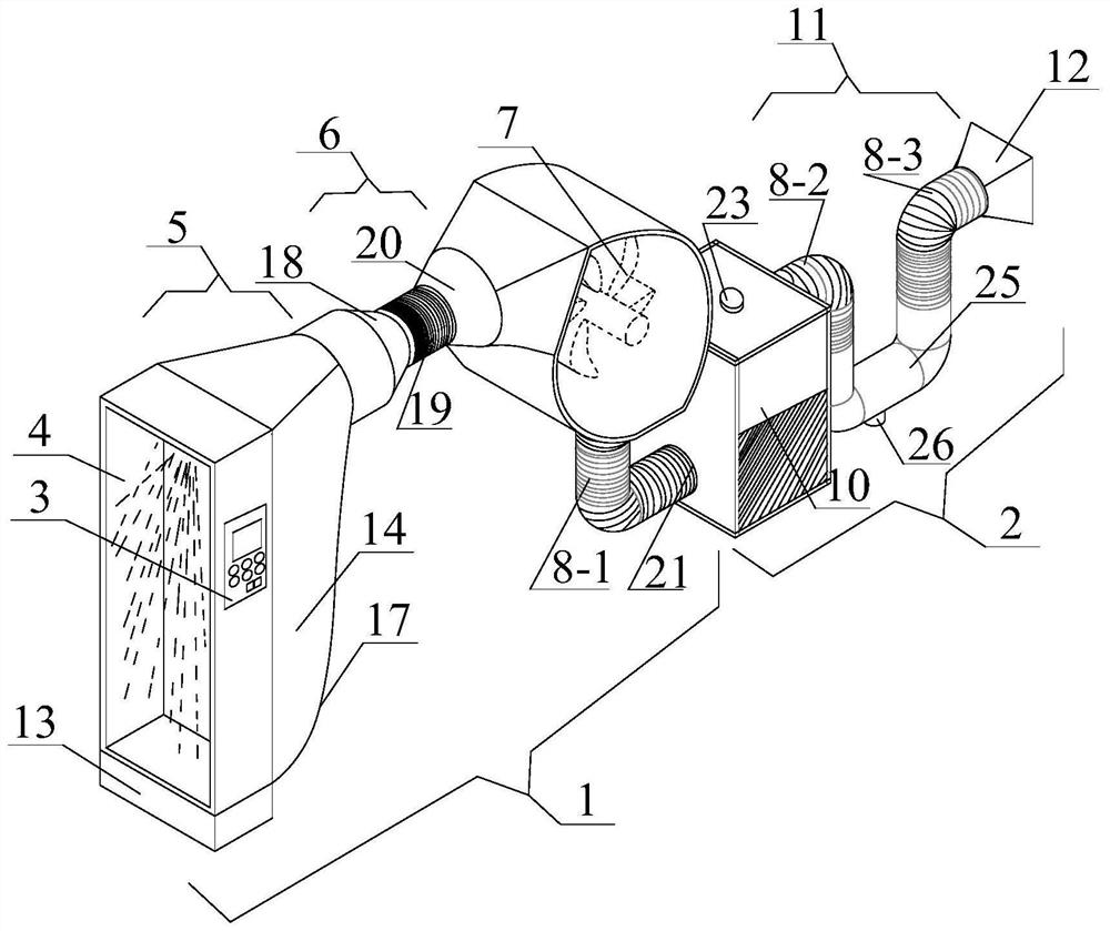
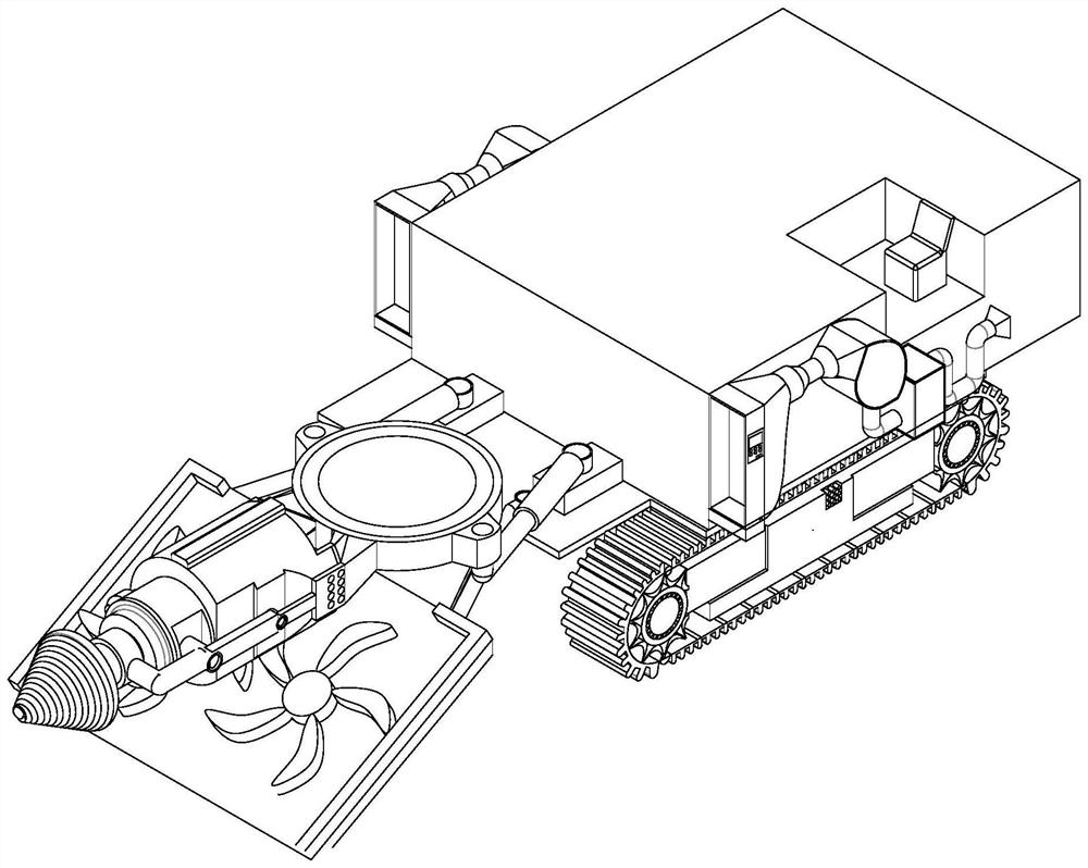
[0018] The invention provides an airborne dust extraction and purification device for a coal mine fully mechanized excavator, such as figure 1 , figure 2 , image 3 As shown, it includes an induction dust extraction mechanism 1 and a sedimentation purification mechanism 2, and the induction dust extraction mechanism 1 and the sedimentation purification mechanism 2 are connected front and rear, wherein the induction dust extraction mechanism includes a mine dust concentration sensor...
PUM
| Property | Measurement | Unit |
|---|---|---|
| Bottom diameter | aaaaa | aaaaa |
| Bottom diameter | aaaaa | aaaaa |
| Diameter | aaaaa | aaaaa |
Abstract
Description
Claims
Application Information