
Clamping structure for semiconductor chip processing

A clamping structure and semiconductor technology, applied in semiconductor/solid-state device manufacturing, electrical components, circuits, etc., can solve the problems of damaged chip adsorption, difficult to control the size of suction, small chip size, etc., to achieve strong stability and improve Adsorption, damage prevention effect

Inactive Publication Date: 2021-10-15
南通迅腾精密设备有限公司
View PDF4 Cites 5 Cited by
  • Summary
  • Abstract
  • Description
  • Claims
  • Application Information

AI Technical Summary

Problems solved by technology

[0005] The object of the present invention is to provide a clamping structure for semiconductor chip processing, which solves the need to measure the quality of the chip in the process of processing the semiconductor chip in the background technology, so as to facilitate the elimination of defective products in advance. The clamping structure is used for clamping and moving, the fixture is in rigid contact with the chip, and the semiconductor chip is a high-precision product, and the chip is easily broken. If it is directly operated by hand, the chip is small in size and difficult to align, and the installation of the chip is easy to be misplaced. The suction force of the wind sucks and clamps the chip, and the magnitude of the suction force is difficult to control. When the suction force is too large, it is easy to damage the adsorption part of the chip due to the strong force. If the suction force is too small, it is easy to cause the chip to fall.

Method used


Image

  • Clamping structure for semiconductor chip processing
  • Clamping structure for semiconductor chip processing
  • Clamping structure for semiconductor chip processing

Examples


Embodiment Construction

[0034] The following will clearly and completely describe the technical solutions in the embodiments of the present invention with reference to the accompanying drawings in the embodiments of the present invention. Obviously, the described embodiments are only some, not all, embodiments of the present invention. Based on the embodiments of the present invention, all other embodiments obtained by persons of ordinary skill in the art without making creative efforts belong to the protection scope of the present invention.

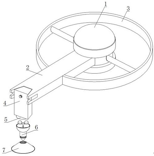
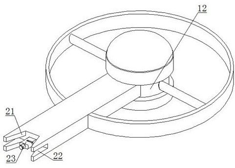
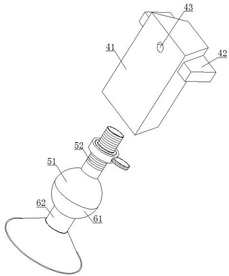
[0035] refer to figure 1 , figure 2 and Figure 9 , a clamping structure for semiconductor chip processing, comprising a rotating base 1 and a clamping extension arm 2 arranged on the surface of the rotating base 1, one end of the clamping extension arm 2 is provided with a clamping end 4, and the rotating base 1 A balance ring 3 is provided on the outer side of the clamping end 4, an extension assembly 5 is provided at the lower end of the clamping end 4, ...


PUM


Abstract

The invention relates to the technical field of chip processing, and discloses a clamping structure for semiconductor chip processing. The clamping structure comprises a rotating base and a clamping extension arm arranged on the surface of the rotating base, one end of the clamping extension arm is provided with a clamping end, the outer side of the rotating base is provided with a balance ring, the lower end of the clamping end is provided with a lifting assembly, an adsorption assembly is arranged in the lower end of the lifting assembly, rubber suction cup is mounted at the lower end of the adsorption assembly, purified water in a second containing ball is sprayed to the inner side of the rubber suction cup in a mist shape from a second spray head along a connecting through pipe, a butt joint column head moves back, a penetrating notch can be seamless through rubber materials, the rubber suction cup is driven by a lead screw to slightly move downwards, the water mist is utilized to improve the adsorption force of the rubber suction cup, so that the rubber suction cup and a chip are tightly jointed, the clamping extension arm can conveniently clamp and move the chip, the clamping stability is relatively high, and the rubber suction cup is made of a soft material, so that the chip can be prevented from being damaged.

Description

technical field [0001] The invention relates to the technical field of chip processing, in particular to a clamping structure for semiconductor chip processing. Background technique [0002] Semiconductor chips are etched and wired on semiconductor sheets to make semiconductor devices that can achieve certain functions. Not only silicon chips, but also semiconductor materials such as gallium arsenide and germanium are common. The electrical properties of the semiconductor must be reliable. Predictable and stable, so the purity of the dopant and the quality of the semiconductor lattice structure must be strictly required. Common quality problems include lattice dislocations, twin planes or stacking faults will affect the characteristics of semiconductor materials . [0003] In the process of processing semiconductor chips, it is necessary to measure the quality of the chip to facilitate the elimination of defective products in advance. If the detection device is directly cla...

Claims


Application Information

Patent Timeline
IPC IPC(8): H01L21/683H01L21/687
CPCH01L21/6838H01L21/687
Inventor 秦小军
Owner 南通迅腾精密设备有限公司
Learn More