Dust cup disassembly and assembly trigger structure with energy-saving and consumption-reducing functions and dust collector
A dust cup and function technology, applied in the field of dust cup disassembly trigger structure and vacuum cleaners, can solve problems such as energy waste, and achieve the effects of reducing the number of charging times, rational structure design, and improving utilization rate
- Summary
- Abstract
- Description
- Claims
- Application Information
AI Technical Summary
Problems solved by technology
Method used
Image
Examples
Embodiment 1
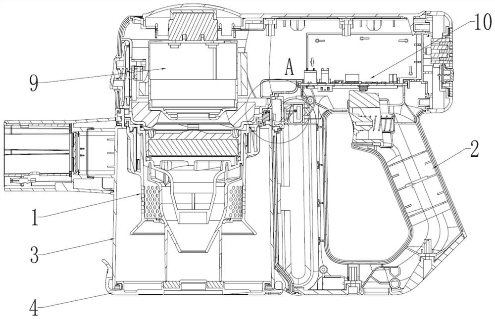
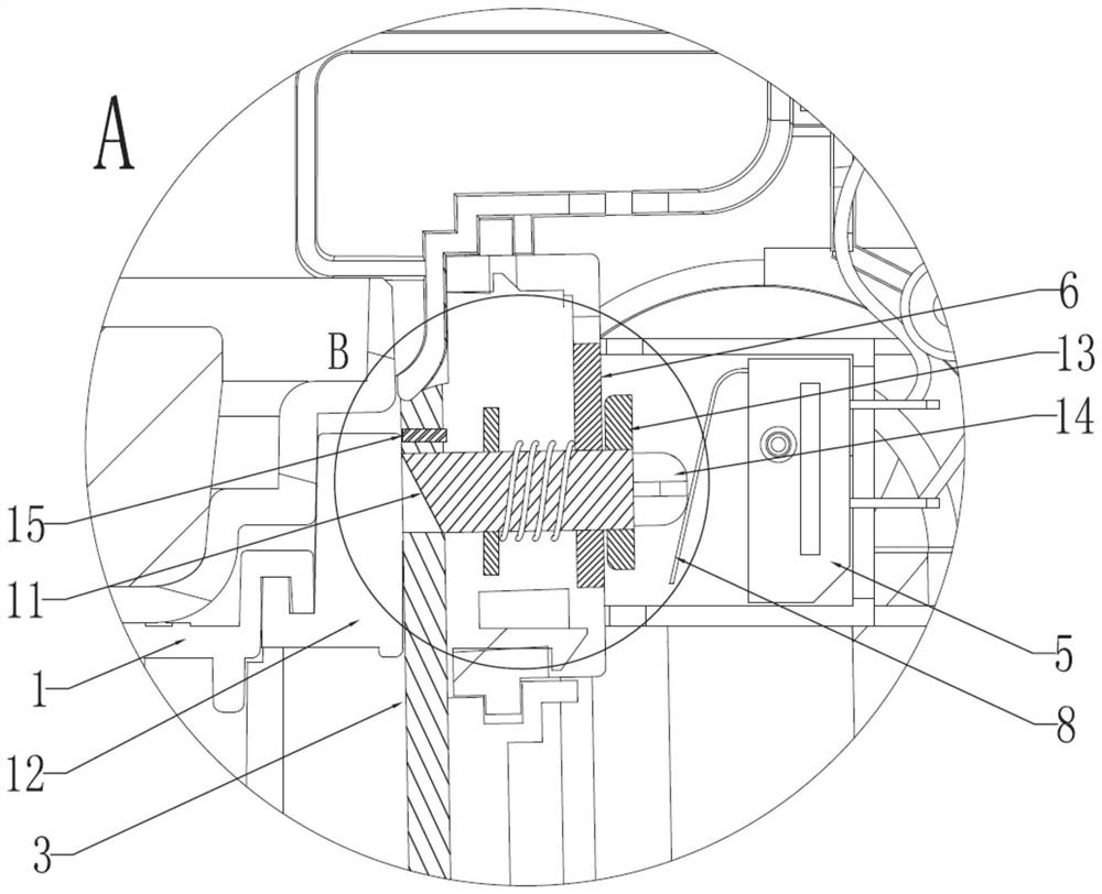
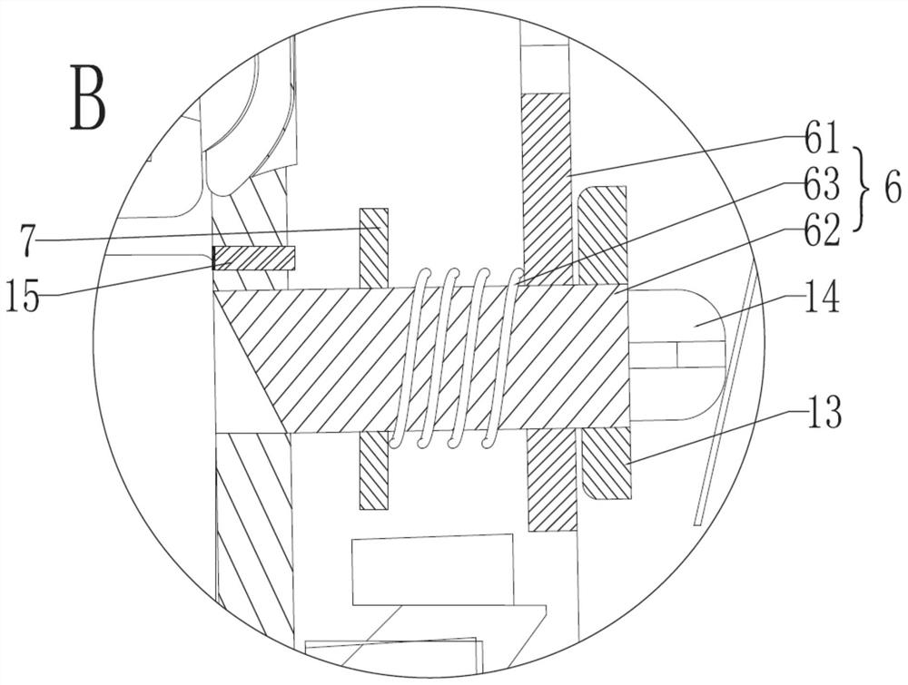
[0031] see Figure 1 to Figure 4 , this embodiment provides a dust cup disassembly and assembly trigger structure with energy saving and consumption reduction functions and a vacuum cleaner, wherein firstly a dust cup body 1 is provided, which is snapped to the dust cup barrel 3 of the fuselage body 2 along the vertical direction Inside, the dust cup cover 4 at the opening of the dust cup barrel 3 is against the bottom of the dust cup body 1, and the dust cup cover 4 is hinged on the edge of the dust cup barrel 3; the micro switch 5 is located in the fuselage body 2, and The micro switch 5 is located on one side of the dust cup bucket 3; the elastic sliding button 6 is located in the fuselage body 2, and the elastic sliding button 6 includes a stopper 61, a slide bar 62 and a spring 63, and the stopper 61 is fixedly connected to the machine body. In the body 2, the slide bar 62 is slidably connected to the block 61, the slide bar 62 is provided with the first boss 7, the sprin...
Embodiment 2
[0039] see Figure 1 to Figure 4 , the figure shows a dust cup disassembly trigger structure and vacuum cleaner with energy-saving and consumption-reducing functions provided by Embodiment 2 of the present invention. This embodiment further makes the following improvements on the basis of the above-mentioned embodiments Technical solution: The end of the slide bar 62 facing the dust cup body 1 is provided with an inclined surface 11 , and the inclined surface 11 gradually slopes downward on the slide bar 62 towards the direction of the micro switch 5 .
[0040] Specifically, see Figure 1 to Figure 4 , the inclination angle of the inclined plane 11 is 50°-60°.
[0041] The setting of the slope 11 facilitates the sliding of the sliding rod 62 triggered by the dust cup body 1 .
Embodiment 3
[0043] see Figure 1 to Figure 4 , the figure shows a dust cup disassembly and assembly trigger structure with energy-saving and consumption-reducing functions and a vacuum cleaner provided by Embodiment 3 of the present invention. This embodiment further makes the following improvements on the basis of the above-mentioned embodiments Technical solution: the dust cup body 1 is surrounded by a card table 12 , and the outer wall of the card table 12 is attached to the inner wall of the dust cup bucket 3 .
[0044] Specifically, see Figure 1 to Figure 4 , the slide bar 62 is against the card table 12, and the distance from the inner wall of the dust cup barrel 3 to the micro switch 5 is equal to the length of the slide bar 62.
[0045] When the dust cup body 1 is installed, the sliding rod 62 is squeezed by the clamping platform 12 to fit the inner wall of the dust cup barrel 3, and at this time the sliding rod 62 just touches the reed 8 so that the reed 8 fits on the micro swi...
PUM
 Abstract
Description
Claims
Application Information
 - R&D
- Intellectual Property
- Life Sciences
- Materials
- Tech Scout
- Unparalleled Data Quality
- Higher Quality Content
- 60% Fewer Hallucinations
Browse by: Latest US Patents, China's latest patents, Technical Efficacy Thesaurus, Application Domain, Technology Topic, Popular Technical Reports.
© 2025 PatSnap. All rights reserved.Legal|Privacy policy|Modern Slavery Act Transparency Statement|Sitemap|About US| Contact US: help@patsnap.com


