Self-connection type high-sealing-performance ball valve

A high-tightness, one-piece technology, applied in valve details, valve devices, valve heating/cooling devices, etc., to achieve the effects of prolonging working life, preventing fluid leakage, and improving wear and tear

Active Publication Date: 2021-10-12
JIANGSU INTELLIGENT SPECIAL VALVE CO LTD
View PDF6 Cites 0 Cited by
  • Summary
  • Abstract
  • Description
  • Claims
  • Application Information

AI Technical Summary

Problems solved by technology

[0006] Aiming at the problems existing in the prior art, the object of the present invention is to provide a self-joined high-tightness ball valve, which can be provided with a corresponding joint-type sealing ring on the side of the valve core close to the water inlet, and at the same time on the valve core A matching conjoined ring groove is set up. When the fluid is cut off, the conjoined sealing ring just extends into the conjoined ring groove, and uses the characteristics of elastic self-expansion to support and shape the conjoined sealing ring, so as to promote the conjoined sealing ring. The integrated sealing ring can form a high-tight fit with the conjoined ring groove. From the overall view, the valve core and the conjoined sealing ring form a conjoined sealing structure. Compared with the traditional conflicting sealing structure, the present invention The sealing performance of the one-piece sealing structure is significantly improved, and fluid leakage is not easy to occur. At the same time, due to the elastic effect of the one-piece sealing ring, the valve core can significantly improve the wear when it rotates, effectively prolonging the working life of the ball valve and the sealing period.

Method used


Image

  • Self-connection type high-sealing-performance ball valve
  • Self-connection type high-sealing-performance ball valve
  • Self-connection type high-sealing-performance ball valve

Examples


Embodiment 1

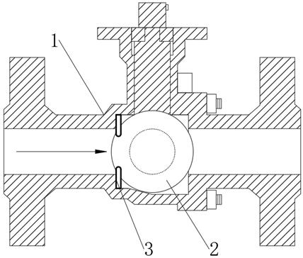
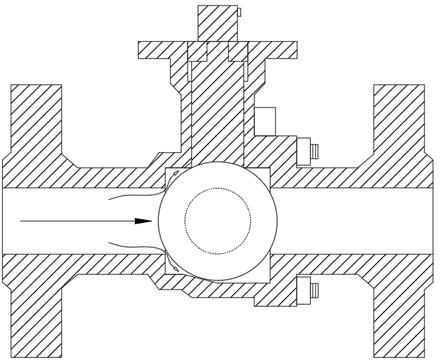
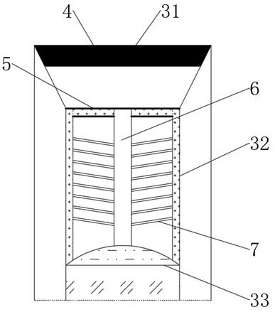
[0043] see Figure 1-3 , a self-joined ball valve with high sealing performance, including a valve body 1, a valve core 2 is movable installed in the valve body 1, a one-piece sealing ring 3 is fixedly connected to the side close to the water inlet in the valve body 1, and the valve core 2 The outer end is provided with a conjoined ring groove 8 corresponding to the one-piece sealing ring 3. The one-piece sealing ring 3 includes a base part 31, a mid-phase change capsule 32 and an inner water storage ring 33, and the base part 31, the mid-phase change capsule 32 and the inner water storage ring 33 are sequentially connected from outside to inside, an electromagnet 4 is installed at the inner end of the base part 31, a separation belt 5 is fixedly connected between the base part 31 and the intermediate phase change capsule 32, and an electric heater is inserted on the separation belt 5 wire 6, and the electric heating wire 6 extends to the inner side of the phase change capsule...


PUM


Abstract

The invention discloses a self-connection type high-sealing-performance ball valve, and belongs to the technical field of ball valves. According to the self-connection type high-sealing-performance ball valve, a corresponding connection type sealing ring is arranged on the side, close to a water inlet, of a valve element, meanwhile, a connection type ring groove matched with the connection type ring groove is formed in the valve element, and when fluid is cut off, the connection type sealing ring just extends into the connection type ring groove; the connection type sealing ring is supported and shaped by utilizing the characteristic of elastic self-expansion so that the connection type sealing ring can be matched with the connection type ring groove with high tightness, and a connection type sealing structure is formed by the valve element and the connection type sealing ring from the whole. Compared with a traditional contact type sealing structure, the sealing performance of the connection type sealing structure is obviously improved, the situation of fluid leakage is not prone to occurring, meanwhile, due to the elastic effect of the connection type sealing ring, the abrasion situation can be obviously improved when the valve element rotates, and the working life and the sealing life of the ball valve are effectively prolonged.

Description

technical field [0001] The invention relates to the technical field of ball valves, in particular to a self-connected high-tightness ball valve. Background technique [0002] Ball valve, the opening and closing part (ball) is driven by the valve stem and rotates around the axis of the ball valve. It can also be used for the regulation and control of fluids, among which the hard-sealed V-shaped ball valve has a strong shear force between its V-shaped ball core and the metal valve seat of surfacing welding carbide, and is especially suitable for fibers and tiny solid particles. etc. medium. The multi-way ball valve can not only flexibly control the confluence, diversion, and flow direction switching of the medium on the pipeline, but also close any channel and connect the other two channels. This type of valve should generally be installed horizontally in the pipeline. According to the driving mode, the ball valve is divided into: pneumatic ball valve, electric ball valve, ...

Claims


Application Information

Patent Timeline
Patent Type & Authority Applications(China)
IPC IPC(8): F16K5/06F16K5/20F16K49/00
CPCF16K5/0689F16K5/0657F16K5/0605F16K5/20F16K5/205F16K49/002
Inventor 沈剑标贺忧
Owner JIANGSU INTELLIGENT SPECIAL VALVE CO LTD
Why Eureka
Try Eureka