
Fly ash mixing and removing system for garbage power plant

A power plant and fly ash technology, applied in the direction of smoke removal, cleaning methods and appliances, chemical instruments and methods, etc., can solve the problems of heavy maintenance workload, reduced bag flowability, high construction cost, etc., to eliminate fugitive emissions , Reduce the amount of equipment maintenance and improve the effect of the workshop environment

Pending Publication Date: 2021-10-19
SHENZHEN ENERGY ENVIRONMENT ENG +6
View PDF0 Cites 0 Cited by
  • Summary
  • Abstract
  • Description
  • Claims
  • Application Information

AI Technical Summary

Problems solved by technology

The bag filter uses a small fan to suck air from the outlet of the mixing machine, and then enters the bag to filter the gas and discharge it directly into the atmosphere. Decreased fluidity, poor negative pressure sealing effect, heavy maintenance workload
Water film dust removal uses a fan to suck air from the air outlet of the mixing machine, introduces it into a water tank, washes the fly ash through water, and then discharges the gas directly into the atmosphere, and the waste water is used to dilute the chelating agent and other recycling. The equipment of this device is complex and the construction cost is high. , covers a large area, and produces waste water, which has the risk of secondary pollution

Method used


Image

  • Fly ash mixing and removing system for garbage power plant
  • Fly ash mixing and removing system for garbage power plant
  • Fly ash mixing and removing system for garbage power plant

Examples


Embodiment Construction

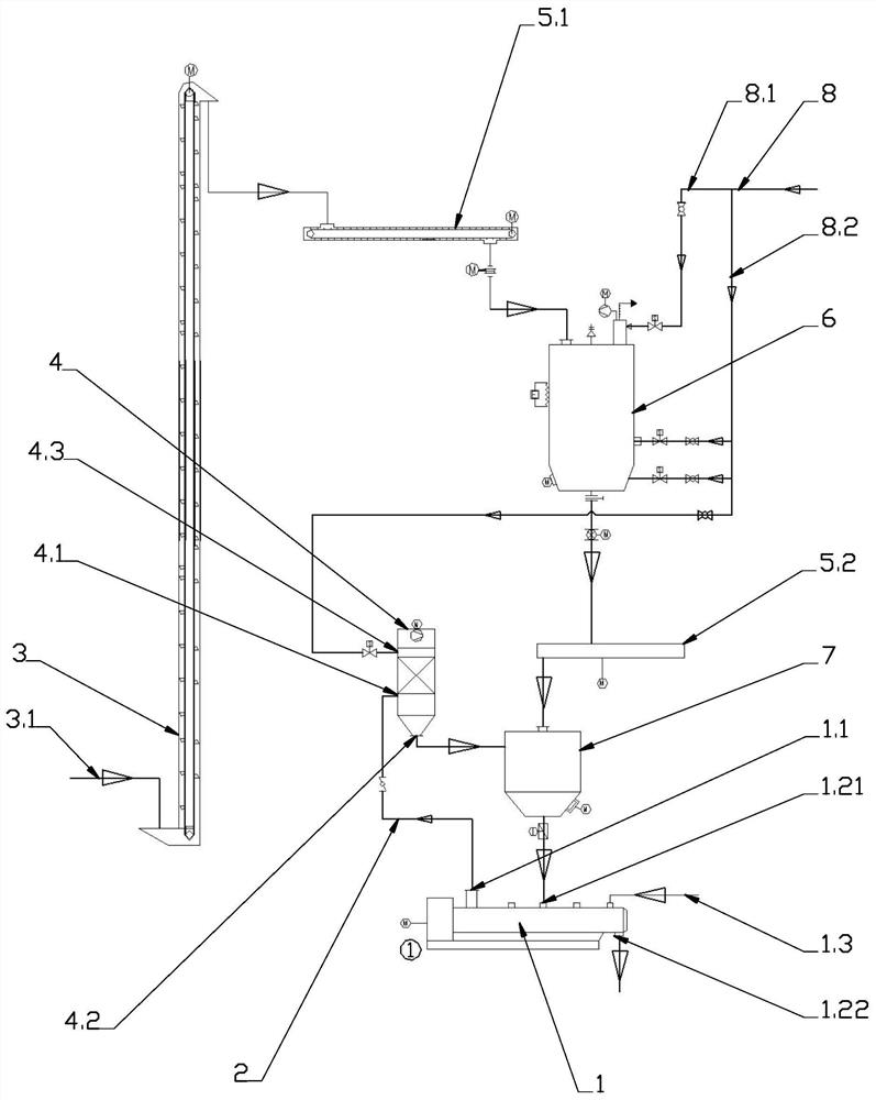
[0021] figure 1 It is a structural schematic diagram of an embodiment of the prior art. As shown in the figure, in the prior art, the fly ash of the garbage power plant enters the bucket elevator 3 through the fly ash conveying pipeline 3.1, and after being lifted by the bucket elevator 3, it is sequentially transported to the ash conveyor 5.1, the fly ash storage bin 6, and weighed The metering bin 7 then enters the mixer 1, and at the same time, the agent is added to the mixer 1 from the agent pipeline 1.3 to stabilize and mix the fly ash, and finally the ash is discharged from the ash discharge port 1.22 after mixing, and then filled after being packed. buried.

[0022] In the above-mentioned fly ash transportation and stabilization mixing process, the link that generates the most dust is the ash unloading and stirring of the mixer. As shown in the figure, the prior art uses the bag filter 4 to process the dust. The fly ash collected by the air outlet 1.1 of the mixing ma...


PUM


Abstract

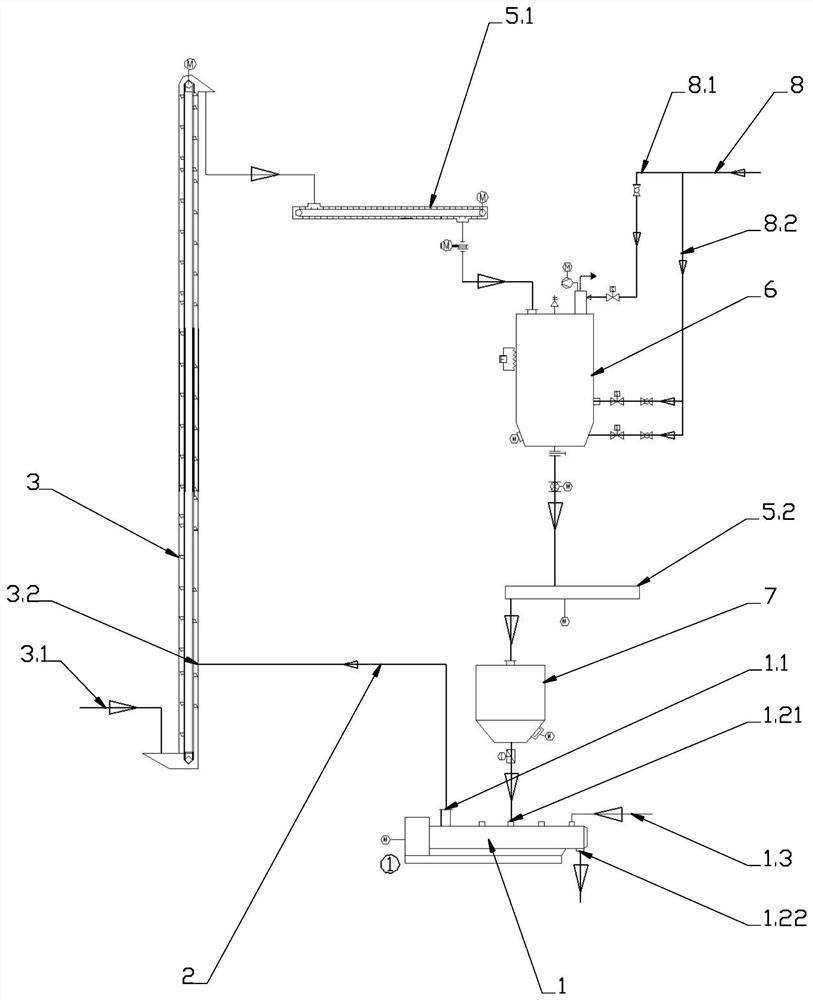
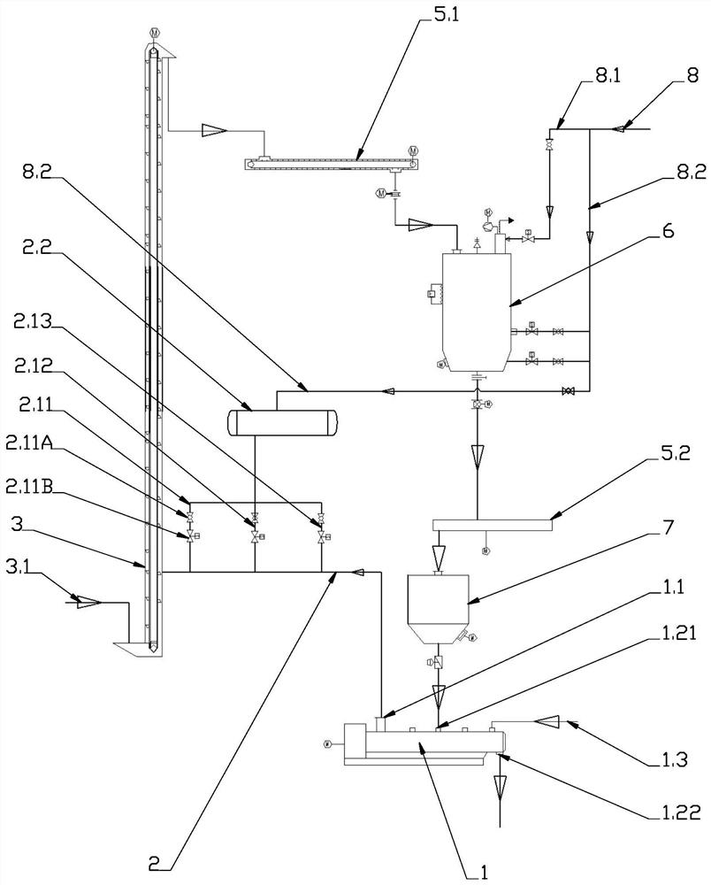
In order to solve the technical problems in the prior art, the invention provides a fly ash mixing and removing system of a garbage power plant. The fly ash mixing and removing system comprises a flying ash collecting and conveying pipeline, wherein the flying ash collecting and conveying pipeline is connected between an air outlet of a fly ash mixing mill and an air suction opening of a bucket elevator, air is sucked from the air outlet of the mixing mill through negative pressure in the bucket elevator (a scraper), a negative pressure environment of the mixing mill is created, and flying dust in the dust discharging and stirring process of the mixing mill is intensively sucked into the bucket elevator (scraper) and then returns to a fly ash storage bin. According to the technical scheme provided by the invention, existing corollary equipment is fully utilized, a large number of equipment facilities do not need to be added, the existing technical problems can be solved only by improving the flying ash collecting and conveying pipeline, the cost is saved, and the dust removal effect is good.

Description

technical field [0001] The invention relates to a dust removal system for a waste incineration power plant, in particular to a fly ash mixing and ash removal system for a waste power plant. Background technique [0002] During the daily operation of waste incineration power plants, fly ash generated during waste incineration needs to be treated. In the document "Technical Specifications for Pollution Control of Domestic Waste Incineration Fly Ash" (HJ1134-2020) released on a trial basis, it is clearly stipulated that the concentration of particulate matter around the fly ash storage and treatment site shall not exceed the emission concentration limit in the "Comprehensive Emission Standards for Air Pollutants" , and requires that measures should be taken to prevent fly ash from flying and spreading during the fly ash treatment process. Fly ash and its processed products should be sealed and equipped with high-efficiency dust removal devices in areas prone to dust generation...

Claims


Application Information

Patent Timeline
Patent Type & Authority Applications(China)
IPC IPC(8): B08B15/04
CPCB08B15/04
Inventor 彭海超李治民
Owner SHENZHEN ENERGY ENVIRONMENT ENG
Learn More