

Magnetorheological porous soft mold and plate forming device
A magnetorheological and soft mold technology, applied in the field of magnetorheological porous soft molds and sheet metal forming devices, can solve problems such as inhomogeneous forming, increase or decrease the inflow of materials, large adjustable range, and improve deformation. The effect of uniformity
- Summary
- Abstract
- Description
- Claims
- Application Information
AI Technical Summary
Problems solved by technology
Method used
Image

Examples
Embodiment 1
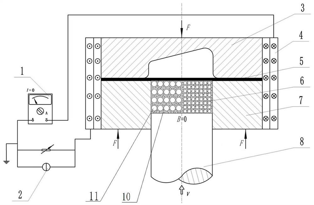
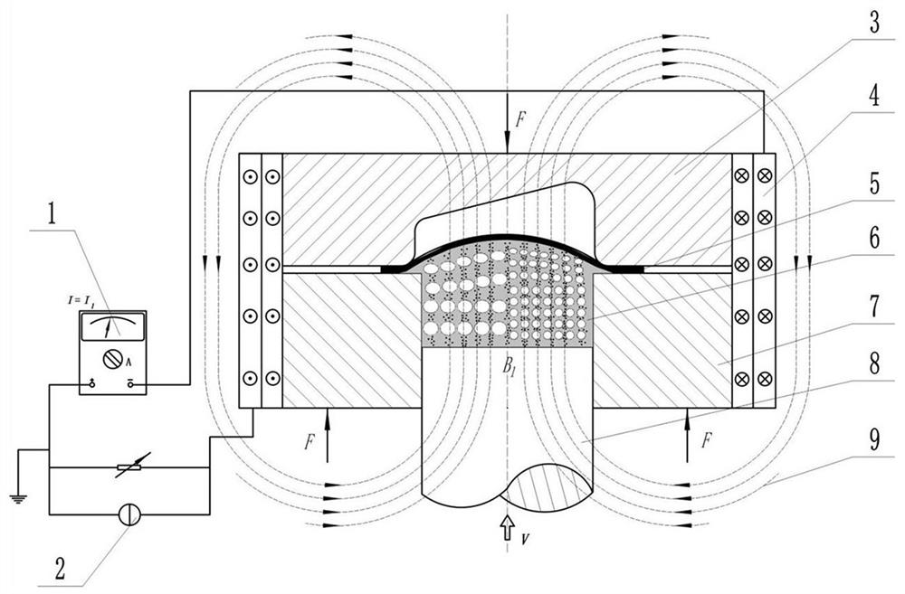
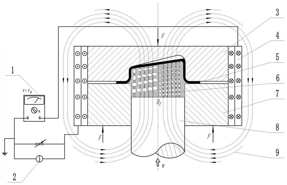
[0063] Such as figure 1 As shown, the plate forming device includes a die 3, a coil 4, a magneto-rheological porous soft die 6, a container frame 7, and a plunger 8. The die 3 is located above the frame 7, and the die 3 is directly opposite to the frame 7. Set so that the die cavity of the die 3 and the inner cavity of the container frame 7 are arranged facing each other. When forming, the plate blank 5 is positioned and installed between the die 3 and the frame 7; the magnetorheological porous soft mold 6 and the plunger The head of 8 is located in the inner cavity of the container frame 7, the coil 4 is set on the outer wall of the container frame 7 and the die 3, and the coil 4 is connected to the DC power supply 2 through the current regulator 1. Wherein, the container frame 7 is a ring structure, and the coil 4 is a copper coil.
[0064] In this embodiment, the magnetorheological porous soft mold 6 includes an elastic matrix and magnetic particles 10, the elastic matrix ...
Embodiment 2
[0084] The difference between this embodiment and Embodiment 1 is that in Embodiment 1, the sizes of the pores 11 in the left forming section are the same, the dimensions of the pores 11 in the right forming section are the same, and the porosity in the left forming section is greater than that in the right forming section. Porosity in the forming section. In this example, if Figure 5 As shown, the sizes of the pores in the left forming section are not exactly the same, and the sizes of the pores in the right forming section are not exactly the same, as long as the porosity in the left forming section is greater than that in the right forming section.
Embodiment 3
[0086]The difference between this embodiment and Embodiment 1 is that in Embodiment 1, pores 11 are provided in both the left forming section and the right forming section, and the porosity in the left forming section is greater than that in the right forming section, so that the left The modulus of elasticity of the forming section is smaller than that of the right forming section. In this embodiment, there are pores in the left forming section, and no pores are provided in the right forming section, so that the elastic modulus of the left forming section is smaller than that of the right forming section.
PUM
| Property | Measurement | Unit |
|---|---|---|
| Particle size | aaaaa | aaaaa |
Abstract
Description
Claims
Application Information