Drilling device for wind power flange forging stock based on wind power type scrap collection
A drilling device and wind power technology, applied in the direction of boring/drilling, drilling/drilling equipment, maintenance and safety accessories, etc., can solve the problems of cumbersome cleaning, increased difficulty of debris recovery, and easy attachment to people Clothes are brought out and other problems to achieve the effect of improving stability and quality
- Summary
- Abstract
- Description
- Claims
- Application Information
AI Technical Summary
Problems solved by technology
Method used
Image
Examples
Embodiment 1
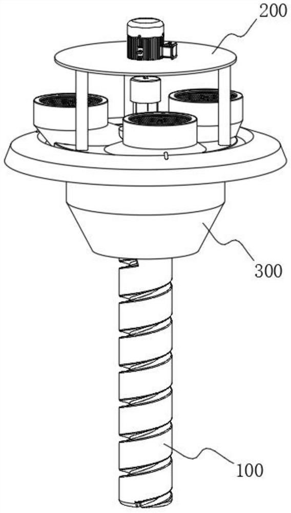
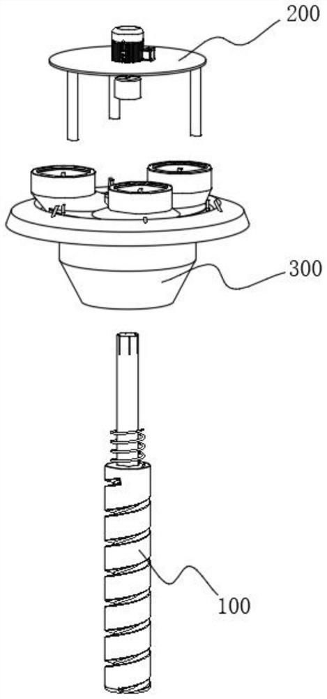
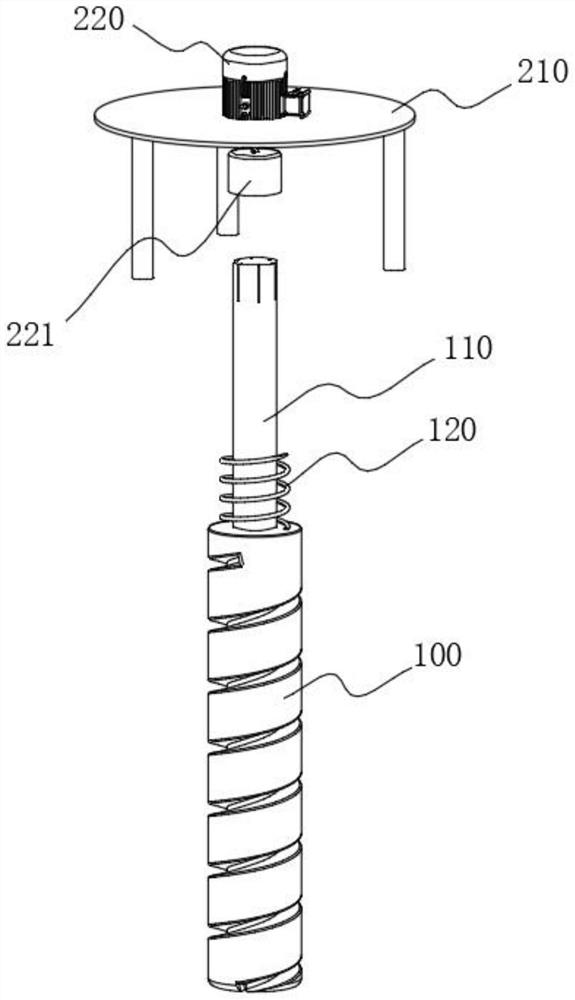
[0043] see Figure 1-Figure 3 As shown, the purpose of this embodiment is to provide a drilling device based on wind-powered debris collection for wind power flange forging blanks, including a drill bit 100 and a drive assembly 200 arranged on the top of the drill bit 100. The drive assembly 200 includes a motor 220, and the motor 220 The outside of the fixed frame 210 is provided with a fixed frame 210, and the specific fixed frame 210 is connected and fixed with the housing 310. The bottom of the fixed frame 210 is provided with a drill bit 100, and the outside of the drill bit 100 is provided with a debris collection mechanism 300. Please refer to Figure 4 As shown, the debris collection mechanism 300 includes at least:
[0044] Housing 310, the housing 310 is arranged on the top of the drill bit 100, the bottom of the motor 220 is provided with an output pipe 221, the top of the drill bit 100 is provided with a sliding shaft 110, and the sliding shaft 110 and the output p...
Embodiment 2
[0050] In order to make the drill bit 100 eject quickly, the difference between this embodiment and Embodiment 1 is that please refer to Figure 6 As shown, wherein: the housing 310 includes a sliding joint housing 311, the bottom wall of the sliding joint housing 311 is slidably connected with the drill bit 100, and the top of the drill bit 100 is located on the outside of the sliding shaft 110. The drill bit 100 on the top wall of the blue ejects quickly, avoiding that the drill bit 100 continues to rotate to cause damage to the opened hole wall, and also can ensure that the output wheel 321 breaks away from the transmission wheel 3221 in time, so that it can be used next time.
Embodiment 3
[0052] In order to carry out secondary collection of debris that cannot be collected by the collection cover 330, the difference between this embodiment and Embodiment 1 is that please refer to Figure 7 As shown, wherein: a connection case 312 is provided between the sliding connection case 311 and the fan case 313, and the bottom fan blade 130 is arranged inside the connection case 312, and the bottom fan blade 130 and the sliding shaft 110 are in a position-limiting sliding connection, and the bottom fan blade An adapter frame 131 is provided at the bottom of the blade 130 , and the adapter frame 131 is rotatably connected to the bottom fan blade 130 , and a plurality of air grooves 3121 are formed in a ring shape on the outer wall of the connecting shell 312 .
[0053] In specific use of this embodiment, on the basis of Embodiment 1, the rotation of the sliding shaft 110 drives the rotation of the bottom fan blade 130, thereby using the wind force generated by the rotation ...
PUM
 Abstract
Description
Claims
Application Information
 - R&D
- Intellectual Property
- Life Sciences
- Materials
- Tech Scout
- Unparalleled Data Quality
- Higher Quality Content
- 60% Fewer Hallucinations
Browse by: Latest US Patents, China's latest patents, Technical Efficacy Thesaurus, Application Domain, Technology Topic, Popular Technical Reports.
© 2025 PatSnap. All rights reserved.Legal|Privacy policy|Modern Slavery Act Transparency Statement|Sitemap|About US| Contact US: help@patsnap.com


