Eureka AIR delivers breakthrough ideas for toughest innovation challenges, trusted by R&D personnel around the world.

Impressing device of photogravure press

A gravure printing machine, printing plate cylinder technology, applied in gravure rotary printing machines, printing machines, rotary printing machines, etc., can solve the difference between the amount of ink and the capacity of the mesh, the ink can not be completely transferred to the top, and the graphic printing is saturated To avoid problems such as color difference, to achieve the effect of avoiding color difference, convenient printing and adjustment machine operation, and large area

Pending Publication Date: 2021-10-19
温州鸿涛包装有限公司
View PDF0 Cites 2 Cited by
  • Summary
  • Abstract
  • Description
  • Claims
  • Application Information

AI Technical Summary

Problems solved by technology

[0003] In the existing gravure printing embossing process, the contact area between the impression cylinder and the plate cylinder is usually small. During embossing, the time for the embossing cylinder to press the substrate onto the plate cylinder is short and the area is small , in the process of high-speed embossing, the ink in the cell may not be completely transferred to the top, resulting in a difference between the amount of ink on the substrate and the capacity of the cell, which may easily lead to color difference in the printed image or even blank printing. The saturation of graphic printing is poor, and the effect of graphic printing is poor. For this reason, we have proposed an embossing device for a gravure printing machine.

Method used


Image

  • Impressing device of photogravure press
  • Impressing device of photogravure press
  • Impressing device of photogravure press

Examples


Embodiment

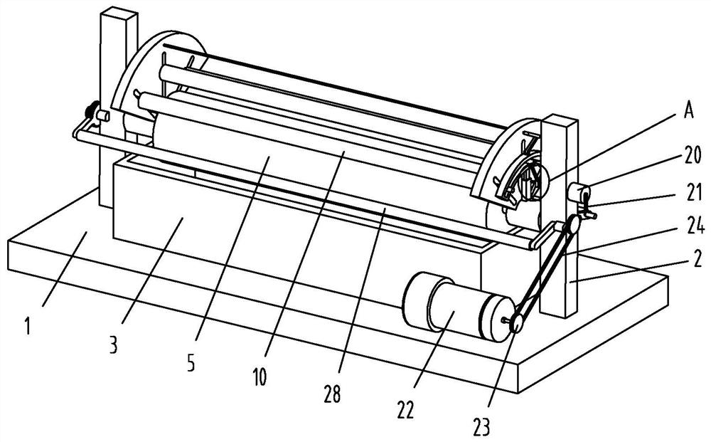
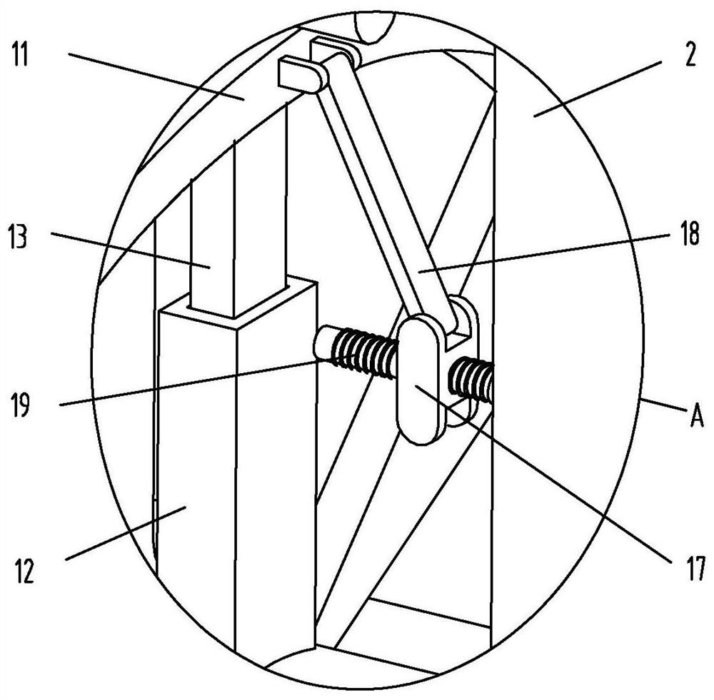
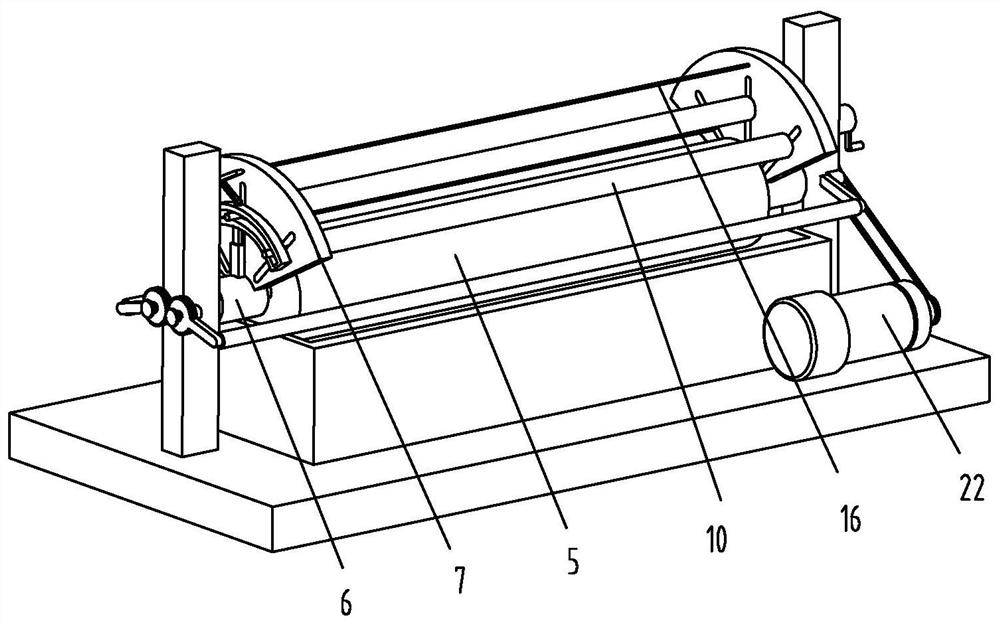
[0042] Example: Reference Figure 1-8 The embossing device of the gravure printing machine shown includes a bottom plate 1 . The base plate 1 may be any base structure in the prior art, such as a metal plate body.

[0043] Two support beams 2 are installed on the top side of base plate 1, and motor 22 is installed on the top side of base plate 1, and motor 22 can be any one in the prior art, and the output end of motor 22 is equipped with transmission shaft 4 by transmission mechanism, One end of the drive shaft 4 passes through one of the support beams 2 and is rotatably connected to one side of the other support beam 2 .

[0044] The support beam 2 is fixedly sleeved with a printing plate cylinder 5, which can be any one in the prior art, and the bottom side of the printing plate cylinder 5 extends into the ink tank 3 installed on the base plate 1, two One side of the support beam 2 is equipped with a fixed cylinder 6 movably socketed on the transmission shaft 4, and the t...


PUM


Abstract

The invention discloses an impressing device of a photogravure press, and relates to the field of photogravure printing. The impressing device comprises a bottom plate, two supporting beams are mounted on the top side of the bottom plate, a motor is mounted on the top side of the bottom plate, and a transmission shaft is mounted at the output end of the motor through a transmission mechanism. One end of the transmission shaft penetrates through one supporting beam and is rotationally connected with one side of the other supporting beam. According to the impressing device of the photogravure press, a plurality of impression cylinders are driven by an adjusting mechanism to synchronously and centripetally move, a printing stock is pressed and attached to the surface of a plate cylinder, during impression, the multiple impression cylinders replace a single cylinder for impression, and the impression cylinders press and attach the printing stock to the plate cylinder for a long time and a large area; and the difference between the amount of ink on the printing stock and the capacity of an ink cell due to the fact that ink in the ink cell cannot be completely transferred during high-speed imprinting can be avoided, the color difference of the printed image-text and even the poor saturation degree of image-text printing due to blank printing can be avoided, and the image-text printing effect is good.

Description

technical field [0001] The invention relates to the field of gravure printing, in particular to an embossing device of a gravure printing machine. Background technique [0002] Gravure printing is to make the entire surface of the printing plate be covered with ink, and then use a special scraping mechanism to remove the ink in the blank part, so that the ink only stays in the cells of the graphic part, and then under the action of greater pressure , to transfer the ink to the surface of the substrate to obtain printed matter. Most of the printing plates of modern gravure printing are made on the surface of the round cylinder, and the printing method of round pressing is adopted. Usually, the impression cylinder is on the top, the printing plate cylinder is on the bottom, and the lower part of the printing plate cylinder is dipped In an ink tank, the layout gets its ink from the tank. [0003] In the existing gravure printing embossing process, the contact area between the ...

Claims


Application Information

Patent Timeline
Patent Type & Authority Applications(China)
IPC IPC(8): B41F9/00B41F13/34
CPCB41F9/00B41F13/34
Inventor 毛永升徐立男陈宗河
Owner 温州鸿涛包装有限公司
Why Eureka
Eureka Blog
Learn More