On-site automatic bundling device for I-shaped steel

A technology of I-beam and baler, which is applied in the field of I-beam on-site automatic baler, which can solve the problems of lack of I-beam groups and achieve the effect of ensuring safety and facilitating on-site hoisting

Active Publication Date: 2021-10-19
深圳市工勘基础工程有限公司
View PDF7 Cites 0 Cited by
  • Summary
  • Abstract
  • Description
  • Claims
  • Application Information

AI Technical Summary

Problems solved by technology

[0003] The purpose of the present invention is to provide an automatic strapping device for I-beams on site, aiming to solve the problem of lack of simple and effective binding of I-beams on the construction site in the prior art. Problems with the device that does the bundling

Method used


Image

  • On-site automatic bundling device for I-shaped steel
  • On-site automatic bundling device for I-shaped steel
  • On-site automatic bundling device for I-shaped steel

Examples


Embodiment Construction

[0025] In order to make the object, technical solution and advantages of the present invention clearer, the present invention will be further described in detail below in conjunction with the accompanying drawings and embodiments. It should be understood that the specific embodiments described here are only used to explain the present invention, not to limit the present invention.

[0026] The implementation of the present invention will be described in detail below in conjunction with specific embodiments.

[0027] In the drawings of this embodiment, the same or similar symbols correspond to the same or similar components; The indicated orientation or positional relationship is based on the orientation or positional relationship shown in the drawings, and is only for the convenience of describing the present invention and simplifying the description, rather than indicating or implying that the referred device or element must have a specific orientation, or in a specific orien...


PUM


Abstract

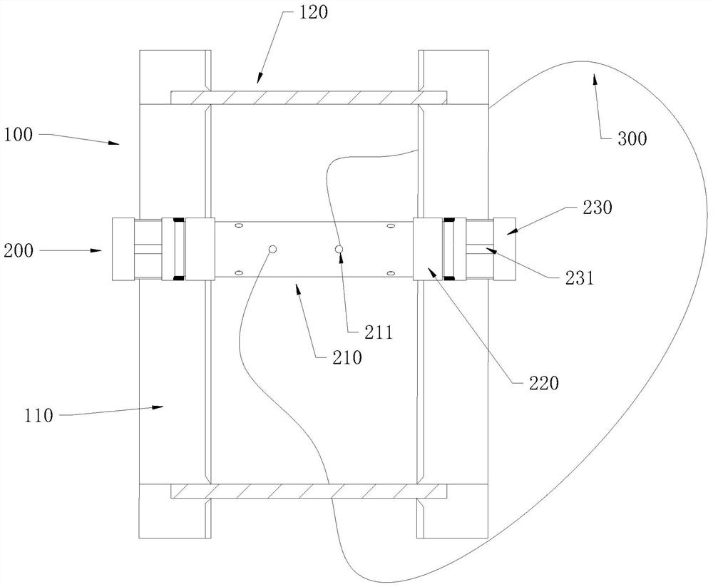
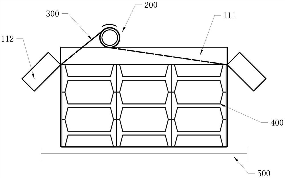
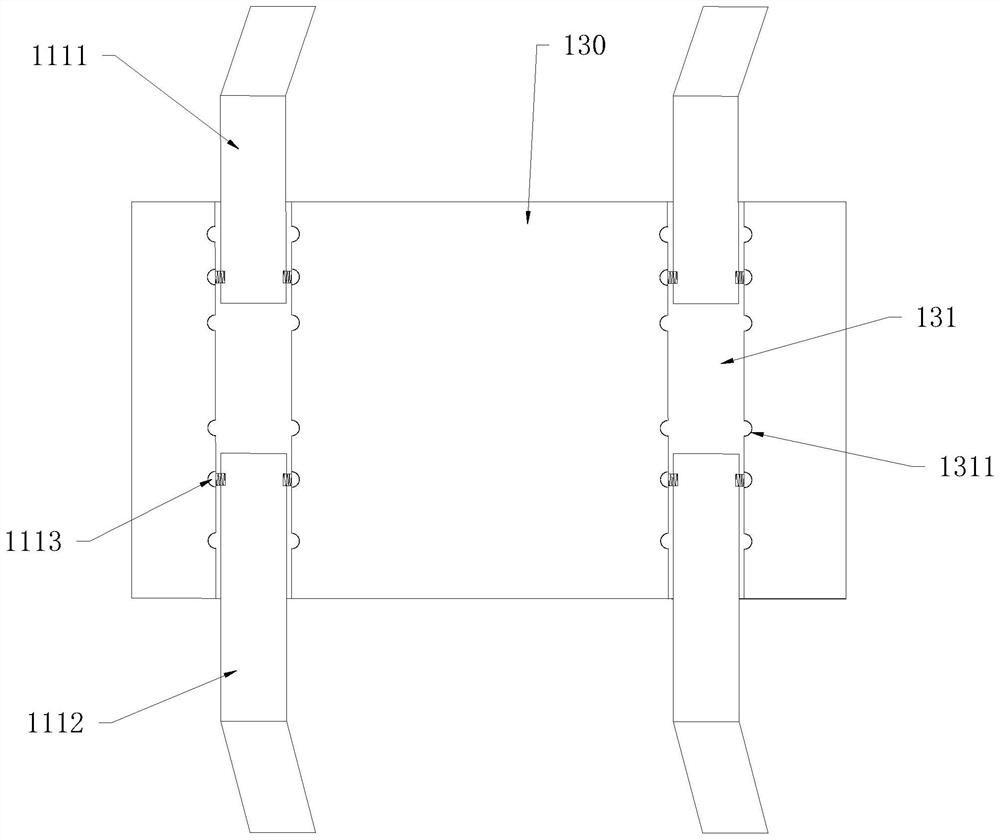
The invention relates to the technical field of building construction, and discloses an on-site automatic bundling device for I-shaped steel. The on-site automatic bundling device for the I-shaped steel comprises a fixing frame, a rotating rolling shaft and a steel wire rope. The fixing frame comprises two frame strips arranged in parallel, the rotating rolling shaft is arranged between the two frame strips, penetrating holes are formed in the rotating rolling shaft, and the two ends of the steel wire rope are arranged in the penetrating holes in a penetrating mode. A surrounding section surrounding an I-shaped steel group is defined by the middle part of the steel wire rope. By rotating the rotating rolling shaft, the surrounding section is pulled and shortened, and the I-shaped steel group is tightly bundled. According to the on-site automatic bundling device for the I-shaped steel, the I-shaped steel group is shaped through the specially designed on-site automatic bundling device for the I-shaped steel, the I-shaped steel group is fixed below the on-site automatic bundling device for the I-shaped steel through the fixing frame, the I-shaped steel group is prevented from moving before bundling, and the I-shaped steel group is shaped by applying force to the rotating rolling shaft and tensioning the steel wire rope, so that follow-up bundling is facilitated; and through the on-site automatic bundling device for the I-shaped steel, a group of I-shaped steel can be conveniently shaped, compacted and bundled on a construction site.

Description

technical field [0001] The patent of the present invention relates to the technical field of building construction, in particular to an on-site automatic strapping device for I-beams. Background technique [0002] When building a construction platform on a construction site, a large amount of I-beam materials are required. After the I-beam is processed and produced by the factory, it is automatically packed and packed by machinery, and transported to the construction site for use. During use, the disassembled I-beams are piled up on site, and the piles are messy after long-term use. When a certain construction site needs to use I-beams, the scattered I-beams are usually temporarily bound with wire ropes or stacked on the hanger, and the I-beams are transported by hoisting. Due to the loose temporary binding, if the hoisting operation is careless, the I-beam is prone to slipping or scattering, which often causes such injury accidents. Contents of the invention [0003] T...

Claims


Application Information

Patent Timeline
Patent Type & Authority Applications(China)
IPC IPC(8): B65B13/32B65B13/20B65B27/10
CPCB65B13/32B65B13/20B65B27/10
Inventor 洪雨娇雷斌李森陈涛蒋鹏王怀妹郑科杰刘浩贤
Owner 深圳市工勘基础工程有限公司
Why Eureka
Try Eureka