
Automatic oil-water separation device for sewage treatment

An automatic separation and sewage treatment technology, which is applied in the direction of liquid separation, separation method, grease/oily substance/floating matter removal device, etc., can solve the problems that oil easily contains water and oil is not completely cleaned, and achieves the effect of improving efficiency

Inactive Publication Date: 2021-10-19
盖明秀
View PDF0 Cites 1 Cited by
  • Summary
  • Abstract
  • Description
  • Claims
  • Application Information

AI Technical Summary

Problems solved by technology

[0003] In view of the above situation, in order to solve the problems existing in the prior art, the purpose of the present invention is to provide an automatic oil-water separation device for sewage treatment, which solves the problems in the prior art that the oil is not completely cleaned and the oil easily contains water.

Method used


Image

  • Automatic oil-water separation device for sewage treatment
  • Automatic oil-water separation device for sewage treatment
  • Automatic oil-water separation device for sewage treatment

Examples


Embodiment Construction

[0025] The specific implementation manners of the present invention will be described in further detail below in conjunction with the accompanying drawings.

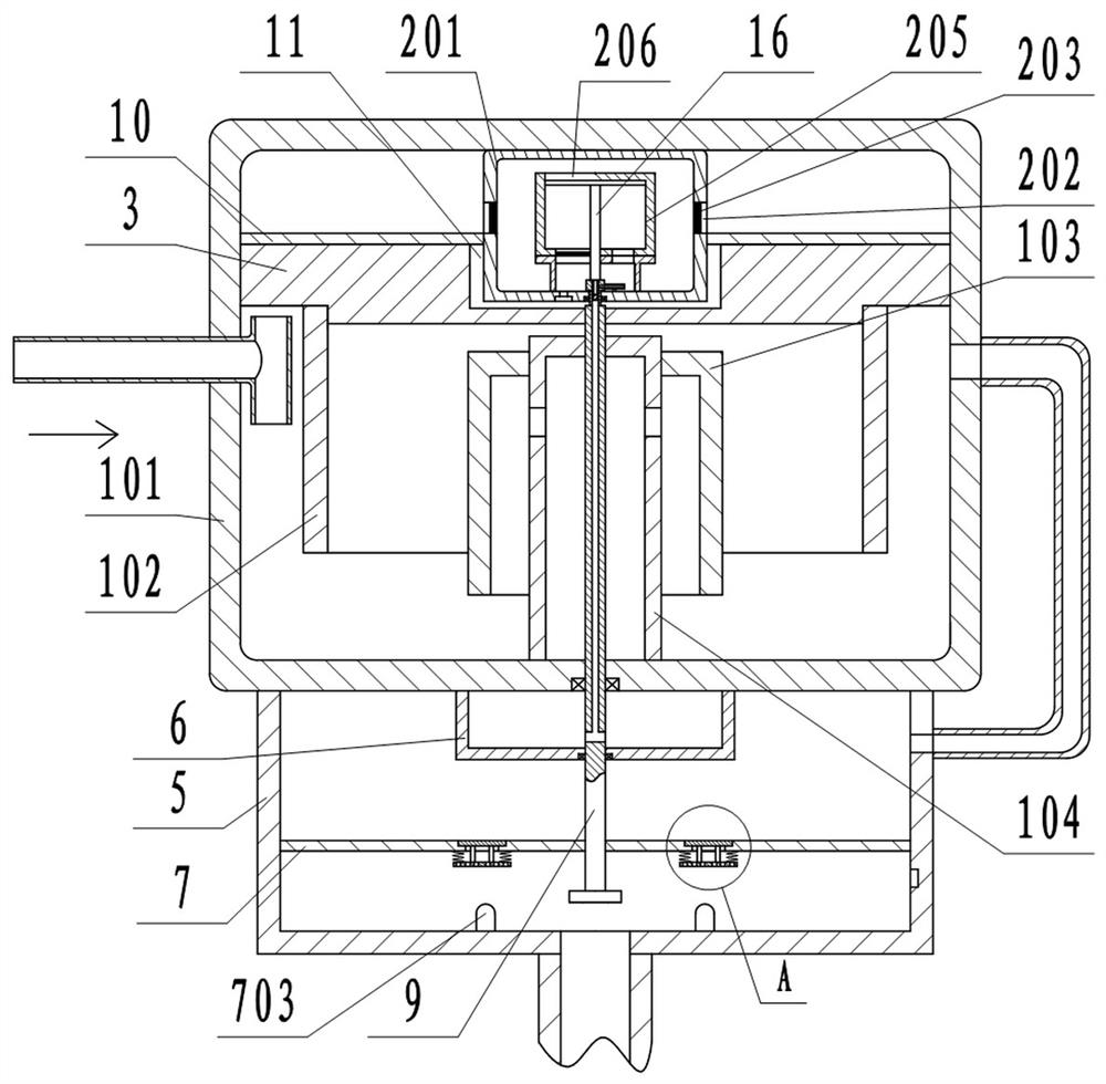
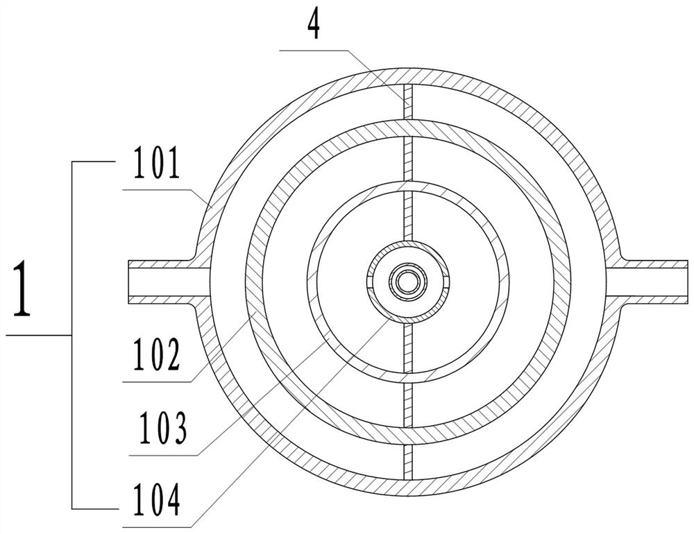
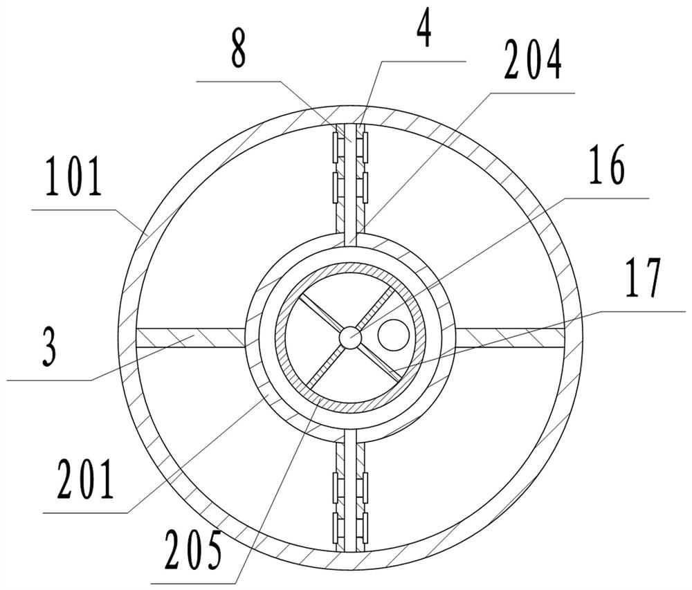
[0026] Depend on Figure 1 to Figure 9 Given, the present invention includes a grease trap 1, an oil filter unit 2, an oil scraper 3, a separator 4, a sump 5 and an oil storage tank 6, and the oil filter unit 2 is located in the grease trap 1 and Close to the top, the partition 4 is located in the middle of the grease trap 1 and placed in the front and rear directions. The partition 4 divides the grease trap 1 into two symmetrical parts. The left and right sides of the partition 4 A liquid passage 8 connecting the grease trap 1 with the oil filter unit 2 is opened on the end face, the water collection pool 5 is located below the grease trap 1, and the water collection pool 5 is provided with a The water baffle 7 that moves up and down, the water baffle 7 divides the sump 5 into two independent chambers up and down, the ...


PUM


Abstract

The invention relates to an automatic oil-water separation device for sewage treatment, and solves the problems that in the prior art, oil cleaning is not thorough, and the oil content easily contains water. According to the technical scheme, the device comprises an oil separation tank, an oil filtering unit, oil scraping plates, a partition plate, a water collection tank and an oil storage tank, wherein the oil filtering unit is located in the oil separation tank, the partition plate is located in the middle of the oil separation tank and divides the oil separation tank into two parts; liquid channels are formed in the left end face and the right end face of the partition plate; the water collection tank is located under the oil separation tank; the water partition plate divides the water collection tank into two cavities; a water outlet of the oil separation tank is communicated with the upper cavity through a pipeline, the oil storage tank is located in the cavity above the oil partition plate and communicated with the oil filtering unit through an oil pipe; the oil scraping plates are arranged on the left side and the right side in the oil separation tank respectively, and the oil scraping plates are close to the lower portion of the oil filtering unit; and the oil scraping plates are in threaded connection with the water partition plate below through a rotating shaft. The device is novel in conception, ingenious in structure and high in practicability.

Description

technical field [0001] The invention relates to the field of sewage treatment machinery, in particular to an automatic oil-water separation device for sewage treatment. Background technique [0002] The existing oil-water separation generally utilizes the difference in specific gravity between suspended solids and water in wastewater to achieve the purpose of separation. The structure of the grease trap mostly adopts the advection type. The oily wastewater enters the rectangular grease trap through the water distribution tank and flows slowly along the horizontal direction. During the flow, the oil floats on the water surface and is pushed by the oil collecting pipe or the oil scraper installed on the pool surface. into the oil collection pipe and flow into the dehydration tank; this method has the following problems: firstly, due to the uncertain amount of collected oil, the position of the oil discharge port cannot be accurately determined; secondly, if the oil is continuo...

Claims


Application Information

Patent Timeline
Patent Type & Authority Applications(China)
IPC IPC(8): C02F1/40B01D17/025B01D17/028
CPCC02F1/40
Inventor 盖明秀
Owner 盖明秀
Learn More