Civil construction engineering structure gap grouting device

A technology of engineering structure and civil construction, which is applied in the construction of buildings, construction, and the processing of building materials, etc., can solve the problems of grouting treatment of gaps affecting the grouting machine, unevenness of the outer wall of the screw, slowing down of rotation speed, etc., so as to speed up the drop The effect of conveying speed, reducing impulse, reducing thrust

Inactive Publication Date: 2021-10-19
NANTONG HUAHUI CONSTR ENG +1
View PDF8 Cites 2 Cited by
  • Summary
  • Abstract
  • Description
  • Claims
  • Application Information

AI Technical Summary

Problems solved by technology

[0002] During the construction of civil engineering structures, the screw grouting machine is used to grout the angle gap of the building structure, and the stirred concrete material is passed into the funnel of the grouting machine, and the material flows along the drainage pipe to the inside of the delivery pipe, and the motor drives The screw rotates to push the material into the gap; in the prior art, when the screw grouting machine is used to grout the gaps of the building structure, because the sand in the concrete material contains a small amount of large stones, the stones will go along with the material. The downward flow continuously impacts the screw, causing uneven potholes on the outer wall of the screw. If the screw is not cleaned in time, the concrete material solidifies inside the potholes, resulting in an increase in the gravity of the screw and a slowdown in the rotation speed, which affects the grouting machine. Grouting

Method used


Image

  • Civil construction engineering structure gap grouting device
  • Civil construction engineering structure gap grouting device
  • Civil construction engineering structure gap grouting device

Examples


Embodiment 1

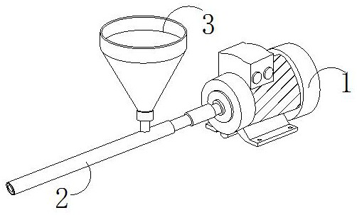
[0029] as attached figure 1 To attach Image 6 Shown:

[0030] The present invention provides a gap grouting device for civil and construction engineering structures. The structure includes a motor 1, a feeding pipe 2, and a funnel 3. The right end of the feeding pipe 2 is horizontally connected to the middle part of the left end of the motor 1, and the bottom of the funnel 3 is installed vertically. On top of delivery tube 2 near the right end.

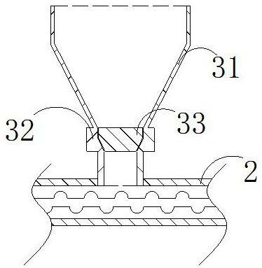
[0031] The funnel 3 includes a funnel body 31 , a connecting block 32 , and a crushing mechanism 33 . The upper surface of the connecting block 32 is fixed on the bottom surface of the funnel body 31 .

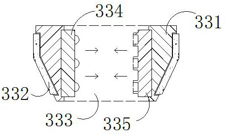
[0032] Wherein, the crushing mechanism 33 includes a support plate 331, a rebound block 332, an opening 333, an impact plate 334, and a matching plate 335. Vertically passing through the upper and lower surfaces of the middle part of the support plate 331, the left side of the impact plate 334 is nested in the left inner wall of t...

Embodiment 2

[0039] as attached Figure 7 to attach Figure 9 Shown:

[0040] Wherein, the feeding pipe 2 includes a pipe body 21, a drainage pipe 22, a screw rod 23, and a diversion mechanism 24, the bottom of the drainage pipe 22 is vertically fixed on the top of the pipe body 21, and the screw rod 23 is arranged inside the pipe body 21, so The surface on both sides of the diversion mechanism 24 is connected with the inner wall of the drainage tube 22 near the bottom end, and the drainage tube 22 is connected with the connection block 32, and the material inside the funnel body 31 is drained to the inside of the tube body 21 through the drainage tube 22, so that The flow diversion mechanism 24 is located near the bottom of the drainage tube 22, and can divide the material and diffuse through the bottom of the drainage tube 22, further increasing the dispersion area of ​​the material.

[0041] Wherein, the diverter mechanism 24 includes a support block 241, a diverter plate 242, a diver...


PUM


Abstract

The invention discloses a civil construction engineering structure gap grouting device. The device structurally comprises a motor, a material conveying pipe and a funnel. Due to the fact that sediments in concrete materials contain a small amount of relatively large stones, the stones continuously impact a screw rod along with downward flowing of the materials, and uneven pits are formed in the outer wall of the screw rod; a crushing mechanism is arranged in a connecting block, and an impact plate and a matching plate in the crushing mechanism are continuously and movably matched to crush the relatively large stones in the materials, so that the impact force of the materials on the screw rod can be reduced, the phenomenon that the pits appear on the outer wall of the screw rod is reduced, the situation that the materials are solidified on the outer wall of the screw rod is reduced, and the screw rod can normally rotate to convey and grout the materials; and due to the fact that a small part of large stones cannot be completely crushed by the crushing mechanism and the same part of the screw rod is prone to being damaged due to the fact that the materials impact the same part of the screw rod for a long time, the materials can be shunted by arranging a shunting mechanism in a drainage pipe, and the diffusion area of the materials is increased.

Description

technical field [0001] The invention belongs to the technical field of building construction, and more specifically relates to a gap grouting device for civil engineering structures. Background technique [0002] During the construction of civil engineering structures, the screw grouting machine is used to grout the angle gap of the building structure, and the stirred concrete material is passed into the funnel of the grouting machine, and the material flows along the drainage pipe to the inside of the delivery pipe, and the motor drives The screw rotates to push the material into the gap; in the prior art, when the screw grouting machine is used to grout the gaps of the building structure, because the sand in the concrete material contains a small amount of large stones, the stones will go along with the material. The downward flow continuously impacts the screw, causing uneven potholes on the outer wall of the screw. If the screw is not cleaned in time, the concrete materi...

Claims


Application Information

Patent Timeline
Patent Type & Authority Applications(China)
IPC IPC(8): E04G21/04
CPCE04G21/0418
Inventor 许亚明刘敏丁俊夏建华黄橙橙唐彦徐毛毛程晓维
Owner NANTONG HUAHUI CONSTR ENG
Why Eureka
Try Eureka