
Simple hydraulic oscillation tool

An oscillating tool, a simple technology, applied in the direction of vibration drilling, etc., can solve the problems of complex structure, short service life, etc., and achieve the effect of good smoothness, large bearing capacity and strong flexibility

Active Publication Date: 2021-10-19
NORTHEAST GASOLINEEUM UNIV
View PDF12 Cites 0 Cited by
  • Summary
  • Abstract
  • Description
  • Claims
  • Application Information

AI Technical Summary

Problems solved by technology

[0004] The purpose of the present invention is to provide a simple hydraulic oscillation tool, this hydraulic oscillation system is used to solve the problems of complex structure and short service life in the current method of using hydraulic power to generate radial vibration

Method used


Image

  • Simple hydraulic oscillation tool
  • Simple hydraulic oscillation tool
  • Simple hydraulic oscillation tool

Examples


Embodiment Construction

[0031] Below in conjunction with accompanying drawing, the present invention will be further described:

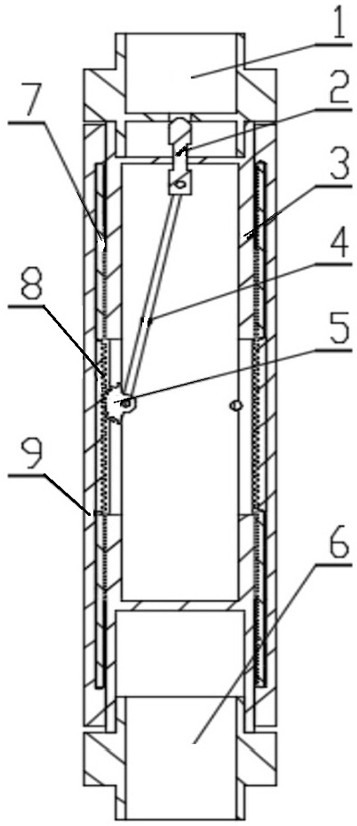
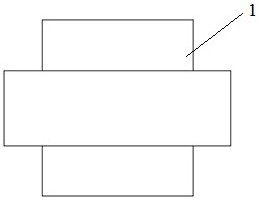
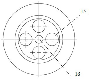
[0032] combine Figure 1-Figure 12 As shown, this hydraulic oscillating tool includes a current-limiting upper joint 1, a current-limiting push head 2, a protective inner cylinder 3, a linkage rod 4, a driving gear 5, a driven rack 8, a ring wall disc spring 7, and a moving outer Cylinder 9, lower connecting tube 6, current-limiting upper connecting tube 1 is threadedly connected above the protection inner tube 3, the lower part of the protective inner tube 3 is threadedly connected with the upper end of the lower connecting tube 6, the lower end of the current-limiting upper connecting tube 1 has an annular step outside, and the lower end There is the same annular step on the outside of the upper end of the receiving tube 6, and the moving outer tube 9 surrounds the outside of the protective inner tube 3 and falls freely on the annular step outside the upper end of the lo...


PUM


Abstract

The invention relates to a simple hydraulic oscillation tool. The simple hydraulic oscillation tool comprises a flow-limiting upper connecting cylinder, a flow-limiting push head, a protective inner cylinder, a linkage rod, a driving gear, a driven rack, annular wall disc springs, a moving outer cylinder and a lower connecting cylinder; the flow-limiting upper connecting cylinder, the protective inner cylinder and the lower connecting cylinder are connected in sequence; the protective inner cylinder, an upper separation plate and a lower separation plate thereof form a protective cavity; the moving outer cylinder surrounds the protective inner cylinder, and freely falls on an annular step on the lower connecting cylinder; the moving outer cylinder and the protective inner cylinder form an annular space; an upper port of the moving outer cylinder is positioned below the annular step of the flow-limiting upper connecting cylinder; a semispherical head part of the flow-limiting push head is contacted and matched with a middle runner port in the flow-limiting upper connecting cylinder; the upper end of the linkage rod is hinged with the flow-limiting push head, and the lower end is fixedly connected with the driving gear; the driving gear is hinged with the protective inner cylinder, extends out from a strip hole, and is engaged with the driven rack; and the annular wall disc springs are respectively arranged above and below the driven rack. The simple hydraulic oscillation tool can generate stable axial vibration, and is high in oscillation frequency and low in vibration amplitude.

Description

technical field [0001] The invention relates to a drilling device used in the field of petroleum engineering, in particular to a simple hydraulic oscillation tool. Background technique [0002] At present, drilling in oil fields has developed from the initial vertical wells to directional wells and horizontal wells. Under the double influence of the large displacement inclination and the drilling tool's own gravity, the conventional drilling tools are close to the lower side well wall, resulting in friction during the drilling process. If it is too large, many drilling problems will occur, such as drill string under pressure, drill sticking, etc., which will seriously affect the drilling speed. In order to effectively reduce frictional resistance and reduce drilling accidents, oscillating tools are generally used to convert the static friction between the drilling tool and the well wall into dynamic friction, so as to achieve the purpose of reducing frictional resistance and...

Claims


Application Information

Patent Timeline
IPC IPC(8): E21B7/24
CPCE21B7/24
Inventor 李思琪田胜雷李卓伦李玮赵欢陈卓
Owner NORTHEAST GASOLINEEUM UNIV
Learn More