Turbine capable of achieving direct backing and with primary-secondary moving blade structure

A technology of mother blades and moving blades, which is applied to turbines. It can solve the problems of not being able to have normal consistency, low binding capacity of moving blade cascade of reversing turbine, and low efficiency of reversing turbine, etc.

Active Publication Date: 2021-10-19
HARBIN ENG UNIV
View PDF21 Cites 0 Cited by
  • Summary
  • Abstract
  • Description
  • Claims
  • Application Information

AI Technical Summary

Problems solved by technology

Due to the large size of the marine gas turbine, especially in the final stage of the power turbine, the radius of the outlet casing is close to 1m, and the radius of the hub of the reverse turbine attached to the upper part of the forward turbine is too large, resulting in extremely low consistency of the moving blades of the reverse turbine, which makes the reverse turbine The capacity of the moving blade cascade to bind the airflow is relatively low, and a large-scale airflow separation occurs at the maximum curvature of the suction surface of the moving blade, resulting in low efficiency of the reversing turbine
Since the double-layer blade needs to consider the strength of the lower blade, the upper reverse turbine blade cascade is limited by weight and cannot have normal consistency
Therefore, it is hoped that there will be a reverse turbine that can effectively reduce the flow separation at the back of the blade without greatly improving the quality of the moving blades of the reverse turbine and without damaging the strength of the moving blades of the front turbine. Efficient reverse turbines are even less researched and explored

Method used


Image

  • Turbine capable of achieving direct backing and with primary-secondary moving blade structure
  • Turbine capable of achieving direct backing and with primary-secondary moving blade structure
  • Turbine capable of achieving direct backing and with primary-secondary moving blade structure

Examples


Embodiment Construction

[0019] The present invention is described in more detail below in conjunction with accompanying drawing example:

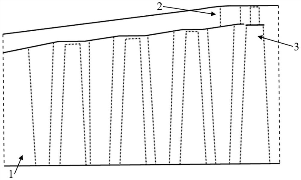
[0020] combine Figure 1-5 , the present invention is made up of reversing turbine mother blade 1, reversing turbine sub-blade 2 and wheel hub 3, the turbine mother blade 1 and sub-blade 2 are evenly installed between the casing and the hub along the circumferential direction, and the wheel hub 3 is the last stage of the front-wheel turbine. Blade tip connecting ring. After the analysis of the internal flow field according to the actual situation, parameters such as the airfoil shape, angle of attack, leading edge radius, and circumferential position of the sub-blade are adjusted to improve power and efficiency as much as possible. The invention adopts the method of cutting the center arc of the mother blade to obtain the sub-blade, keeps the center arc of the mother blade unchanged, and intercepts the center arc of the second half of the blade from the axial pos...


PUM


Abstract

The invention aims to provide a turbine capable of achieving direct backing and with a primary-secondary moving blade structure. The turbine comprises a hub, a backing turbine primary blade and a backing turbine secondary blade, the backing turbine primary blade and the backing turbine secondary blade are uniformly mounted between a casing and the hub in a staggered manner in the circumferential direction, the hub is an ahead turbine last-stage moving blade tip connecting ring, and the trailing edge point of the backing turbine secondary blade and the trailing edge point of the backing turbine primary blade are located at the same axial position; and the distance b2 between the leading edge point and the leading edge frontal line of the backing turbine primary blade is changed by the backing turbine secondary blade according to the flowing working condition, and b2 does not exceed 65% of the axial chord length b1 of the backing turbine primary blade. The primary blade and the secondary blade are arranged in an axial flow turbine moving blade cascade in a staggered manner, the binding capacity of the backing turbine blade cascade on airflow is improved, large-scale separation is reduced, the turbine power and efficiency are improved, and good working reliability is achieved.

Description

technical field [0001] The invention relates to a gas turbine, in particular to a turbine of a marine gas turbine. Background technique [0002] In the field of ship power, the gas turbine is an ideal power equipment, but it cannot be reversed directly to realize the reverse of the ship. In order to make up for this disadvantage, people try to add a reverse turbine to the outside of the final stage of the conventional power turbine to realize the reversal of the power turbine in the gas turbine, that is, the integrated direct reverse turbine is composed of two parts: the forward turbine and the reverse turbine. The reverse turbine has only one stage and is located above the last-stage blade cascade of the forward turbine; the moving blades of the reverse turbine and the last-stage movable blades of the forward turbine are connected through an intermediate ring to form double-layer blades. On the contrary, the purpose of forward and reverse rotation of the turbine is realize...

Claims


Application Information

Patent Timeline
Patent Type & Authority Applications(China)
IPC IPC(8): F01D5/14
CPCF01D5/141F01D5/147Y02T10/62
Inventor 高杰赵天笑王国杰武思宇周成
Owner HARBIN ENG UNIV
Why Eureka
Try Eureka