Crack monitoring equipment and test equipment for automobile fatigue test

A fatigue test and monitoring equipment technology, applied in the direction of applying repeated force/pulsation force to test material strength, measuring devices, instruments, etc., can solve the problem of stopping the test, prolonging the fatigue life of the sample, and unable to achieve real-time monitoring of crack initiation and expansion, etc. problems, to achieve the effect of improving test efficiency

Pending Publication Date: 2021-10-19
CITIC DICASTAL +1
View PDF0 Cites 1 Cited by
  • Summary
  • Abstract
  • Description
  • Claims
  • Application Information

AI Technical Summary

Problems solved by technology

Crack inspection requires a lot of manpower and time costs. At the same time, manual inspection cannot achieve real-time monitoring of crack initiation and expansion, and cannot accurately stop the test when the crack reaches the specified length. Usually, there will be a certain amount of misjudgment that the fatigue life of the sample is extended.
So far, there is no mature crack monitoring system suitable for fatigue testing of automobile chassis parts in China.

Method used


Image

  • Crack monitoring equipment and test equipment for automobile fatigue test
  • Crack monitoring equipment and test equipment for automobile fatigue test
  • Crack monitoring equipment and test equipment for automobile fatigue test

Examples


Embodiment 1

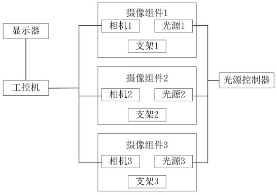
[0023] This Example 1 provides a crack intelligent monitoring system for fatigue testing of automobile chassis components, such as figure 1 As shown in, a light source controller, a industrial computer, a display, and at least one imaging component are included. The number of the imaging assembly is selected according to the test demand of the automotive chassis component fatigue test. In this embodiment, three imaging assemblies (e.g., in other embodiments can be 1, 2, 4, 5, 6, 7) 8, 9, 10, 11, 12, 13-72, etc.). Each of the imaging assemblies includes a camera, a light source, and a bracket, a camera, and a light source, all of which are mounted on the bracket, the camera, the light source, and the bracket is assembled together, according to the test demand of the fatigue test of the automotive chassis components. The location of the camera assembly is installed. Once the camera is a fixed focus lens, the crack length, and the photo pixel are determined, only the calibration leng...

Embodiment 2

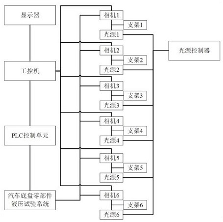
[0032] In this Example 2, a test equipment for automotive chassis component fatigue test, such as image 3 The display, industrial computer, PLC control unit, automotive chassis component hydraulic test system, camera, light source, bracket, light source controller, display and industrial control, there is information interaction between the industrial control and the PLC control unit Information interaction, PLC control unit and the automotive chassis component hydraulic test system, the light source controller and the light source are connected to the light source, the camera and the light source are integrated together, the stent supports the fixed camera and the light source, the camera and the industrial computer There is information interaction between information interaction, the camera takes a sample crack photo of the fatigue test of the car chassis parts.

[0033] The light source controller is electrically connected to the light source, and the light source controller fu...


PUM


Abstract

The invention belongs to the technical field of automobile bench tests, and provides crack monitoring equipment and test equipment for an automobile fatigue test. A camera shooting assembly comprises a camera, a light source and a support, the light source irradiates the surface of a test sample, a light source controller supplies power to the light source, the camera shoots the surface of the test sample. An industrial personal computer comprises a photographing control unit, a test load information acquisition unit, a photo information marking unit and a display control unit, and the crack monitoring equipment can accurately monitor cracks generated in the fatigue test process of automobile chassis parts in real time, can shoot photos of the cracks generated by the tested sample at regular time, and can accurately monitor the whole process of crack initiation and propagation; the test equipment provided with the crack monitoring equipment can control the test to stop according to the crack length, the fatigue life of the tested sample can be accurately obtained, the crack condition of the tested sample can be monitored on line in real time, the test equipment is not limited by people and working time, and the test efficiency is improved.

Description

Technical field [0001] The present application relates to the field of automotive settlement test technologies, and specific to crack monitoring equipment and test equipment for automotive fatigue tests. Background technique [0002] During the development of the vehicle, in order to verify the safety performance of the automobile chassis components, the fatigue and durability test of automotive chassis components must be performed. The fatigue test items and test samples required for automotive chassis components, and the test cycle is long. The main plant will clearly stipulate that the crack length generated by the test sample means that the sample is invalid. After the sample failure needs to stop the test, the different host plants are defined by the determination of whether the crack length definition of the determination of the sample failed. During the test, the cracks produced by the test sample were monitored. At present, most of the laboratory uses manual regular inspe...

Claims


Application Information

Patent Timeline
Patent Type & Authority Applications(China)
IPC IPC(8): G01N3/36G01N3/06
CPCG01N3/36G01N3/068G01N3/06G01N2203/0005G01N2203/0048G01N2203/0066G01N2203/0064G01N2203/0647G01M17/007G01M5/0033G01M99/007G01N21/8806G01N21/8851G01N2021/8854G01N2021/888G01N2021/8887
Inventor 宋盈盈翟龙郝斌斌刘强尹志高阿拉腾房永伟卢星星
Owner CITIC DICASTAL
Why Eureka
Try Eureka