
Lighting control system and method based on environment feedback

A lighting control system and environmental technology, applied in the direction of energy-saving control technology, electrical components, etc., can solve the problems of small application range, pedestrians feel uncomfortable, low usability, etc., to avoid visual discomfort, avoid power transmission, and accurately ensure safe operation Effect

Pending Publication Date: 2021-10-19
JIANGSU LIGEN ELECTRIC POWER ELECTRONICS TECH CO LTD
View PDF0 Cites 0 Cited by
  • Summary
  • Abstract
  • Description
  • Claims
  • Application Information

AI Technical Summary

Problems solved by technology

[0003] The existing control methods based on environmental feedback are still relatively lacking, and for a single control method, the application range is small, the usability is low, and there is a lack of effective feedback control lighting based on the environment. For lighting control, it is impossible to control lighting from input The power supply to the control and then to the output are processed one by one. If one of the processing processes of the lighting control is not perfect, it will affect the output power of the lighting control; the traditional lighting control cannot adjust the interference of the instantaneous change of light (such as short-term corridor or roadside lights) Bright light interference) will not only affect the lighting effect, but also appear stroboscopic, which will make pedestrians feel uncomfortable

Method used


Image

  • Lighting control system and method based on environment feedback
  • Lighting control system and method based on environment feedback
  • Lighting control system and method based on environment feedback

Examples


Embodiment Construction

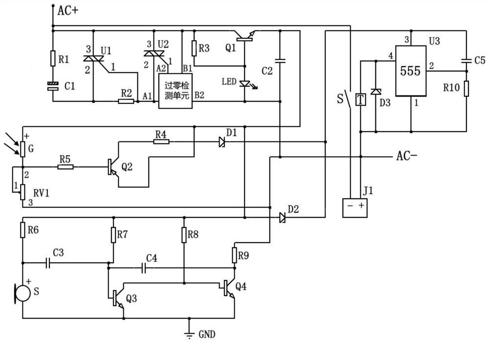
[0036] Such as figure 1 As shown, in this embodiment, a lighting control system based on environmental feedback includes: a dimming control module including a resistor R1, a capacitor C1, a triac U1, a resistor R2 and a triac U2.

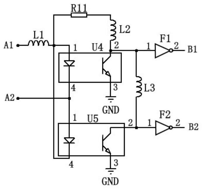
[0037] The zero-crossing detection unit includes an inductor L1, a coupler U4, a coupler U5, a resistor R11, an inductor L2, an inductor L3, a NOT gate F1 and a NOT gate F2. ,

[0038] The voltage stabilizing unit includes a resistor R3, a transistor Q1, a lamp LED and a capacitor C2.

[0039] The brightness sensing module includes a brightness sensor G, a variable resistor RV1, a resistor R5, a transistor Q2, a resistor R4, and a diode D1.

[0040] The voice-activated sensing module includes a resistor R6, a capacitor C3, a resistor R7, a resistor R8, a capacitor C3, a capacitor C4, a resistor R9, a transistor Q4, a transistor Q3 and a voice-activated sensor S.

[0041] The delay trigger module includes a relay T, a trigger switch S, a diode D3,...


PUM


Abstract

The invention discloses a lighting control system and method based on environment feedback. The system comprises a dimming control module, a brightness sensing module, a sound control induction module and a delay trigger module; the dimming control module is used for controlling the on and off of a lighting system and the adjustment of the brightness through the cooperation of a bidirectional thyristor U1 and a bidirectional thyristor U2; the brightness sensing module is used for acquiring the conduction voltage of the dimming control module and controlling the on-off of the voltage according to the feedback of ambient brightness; the sound control induction module is connected in parallel with the brightness sensing module, obtains the conduction voltage of the dimming control module, and controls the on-off of the voltage through the feedback of ambient sound; the delay trigger module is used for receiving two paths of electric signals of the brightness sensing module and the sound control induction module and controlling the output of a lighting voltage through delay trigger; and interference of light instantaneous change is prevented through the delay trigger, and the ambient feedback is received to adjust the operation state of the lighting control system.

Description

technical field [0001] The invention relates to the technical field of environmental feedback control, in particular to a lighting control system and method based on environmental feedback. Background technique [0002] Environmental feedback feeds back the changed environmental state through the change of the environment, and feedback is the process of returning the output of the system to the input and changing the input in a certain way, thereby affecting the system function, for example, the response to the environmental stress situation; through Sensors receive environmental feedback to change the state (temperature, humidity, lighting) in the environment, and then need to establish a control path for environmental feedback. [0003] The existing control methods based on environmental feedback are still relatively lacking, and for a single control method, the application range is small, the usability is low, and there is a lack of effective feedback control lighting bas...

Claims


Application Information

Patent Timeline
Patent Type & Authority Applications(China)
IPC IPC(8): H05B45/10H05B45/12H05B45/50H05B47/11H05B47/12H05B47/105H05B47/20
CPCH05B45/10H05B45/12H05B45/50H05B47/11H05B47/12H05B47/105H05B47/20Y02B20/40
Inventor 钱昶
Owner JIANGSU LIGEN ELECTRIC POWER ELECTRONICS TECH CO LTD
Learn More