
Brushless motor control method and device for intelligent dust collector

A technology for intelligent vacuum cleaners and brushless motors, applied in vacuum cleaners, electromechanical devices, current controllers, etc., can solve problems such as poor heat dissipation, time-consuming and laborious adjustment, installation and disassembly of brushless motors, etc., to prolong service life and ensure operation , Easy and fast installation

Inactive Publication Date: 2021-10-22
深圳市伽兰德科技有限公司
View PDF6 Cites 0 Cited by
  • Summary
  • Abstract
  • Description
  • Claims
  • Application Information

AI Technical Summary

Problems solved by technology

[0003] Existing brushless motor control methods for smart vacuum cleaners cannot adjust the running state of brushless motors based on past and current operating data. Existing brushless motor control devices for smart vacuum cleaners usually use fixing bolts to control The box is fixedly installed, and it is time-consuming and laborious to install and disassemble, and the brushless motor control device only dissipates heat through the heat dissipation port, and the heat dissipation effect is poor

Method used


Image

  • Brushless motor control method and device for intelligent dust collector
  • Brushless motor control method and device for intelligent dust collector
  • Brushless motor control method and device for intelligent dust collector

Examples


Embodiment Construction

[0034] The following will clearly and completely describe the technical solutions in the embodiments of the present invention with reference to the accompanying drawings in the embodiments of the present invention. Obviously, the described embodiments are only some, not all, embodiments of the present invention.

[0035] In describing the present invention, it should be understood that the terms "upper", "lower", "front", "rear", "left", "right", "top", "bottom", "inner", " The orientation or positional relationship indicated by "outside", etc. is based on the orientation or positional relationship shown in the drawings, and is only for the convenience of describing the present invention and simplifying the description, rather than indicating or implying that the referred device or element must have a specific orientation, so as to Specific orientation configurations and operations, therefore, are not to be construed as limitations on the invention.

[0036] refer to Figure ...


PUM


Abstract

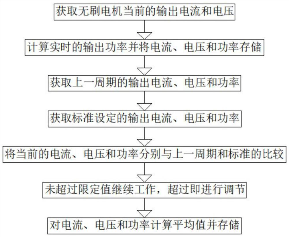
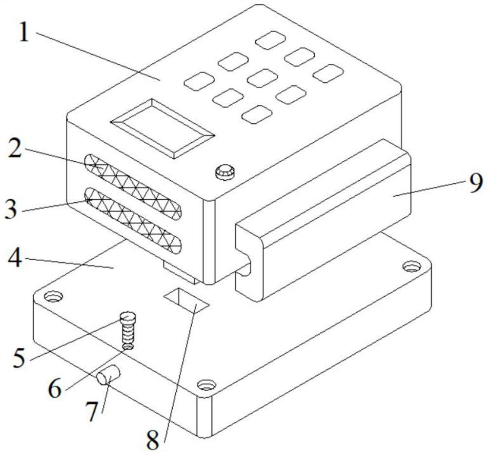
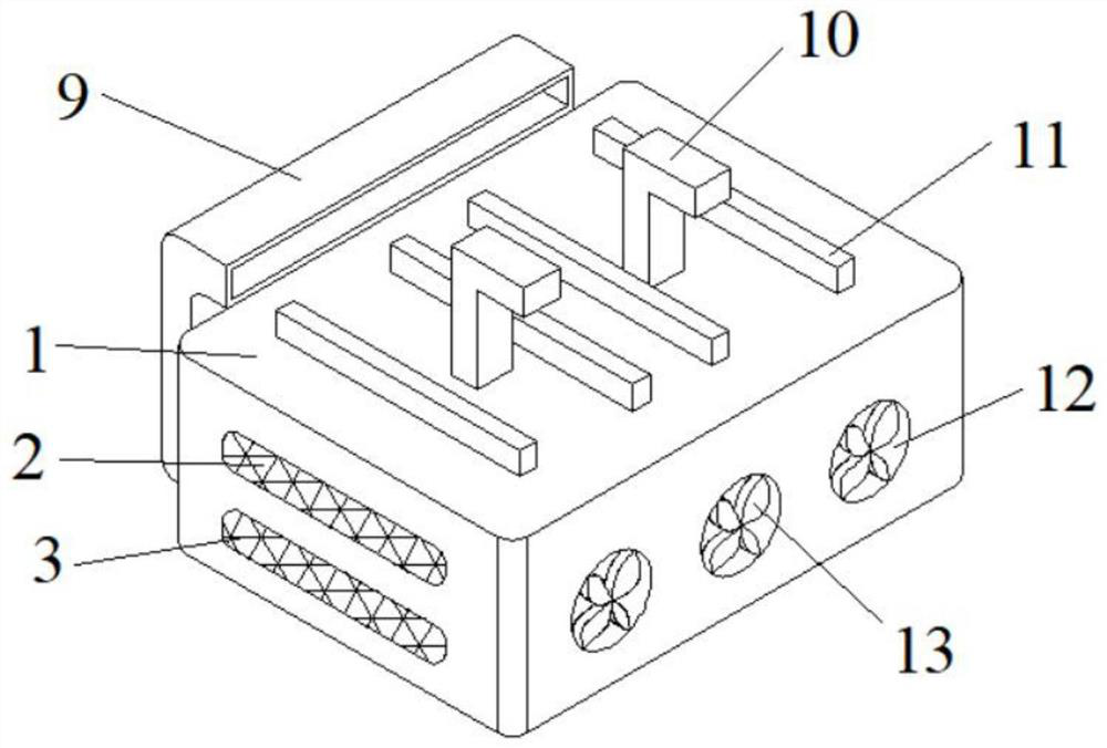
The invention belongs to the technical field of dust collectors, particularly relates to a brushless motor control method and device for an intelligent dust collector, and aims to solve the problem of troublesome installation. The device comprises a control box and an installation plate, an air inlet is formed in one side of the control box, a fan is installed on the air inlet, the side, opposite to the air inlet, of the control box communicates with an air inducing channel, heat dissipation openings are formed in the two sides, adjacent to the air inlet, of the control box correspondingly, heat dissipation fins are longitudinally installed at the bottom of the control box, L-shaped insertion rods are vertically welded to the two sides of the middle of the bottom of the control box correspondingly, and a locking mechanism for fixing the control box is arranged in the installation plate. According to the invention, the operation state of the brushless motor can be adjusted according to previous and set operation data, normal operation of the brushless motor is ensured, the control box is convenient and rapid to mount and dismount, time-saving and labor-saving, multiple heat dissipation means are provided, and the heat dissipation means cooperate with each other and supplement each other, so that the heat dissipation effect is better.

Description

technical field [0001] The invention relates to the technical field of vacuum cleaners, in particular to a brushless motor control method and device for intelligent vacuum cleaners. Background technique [0002] The smart vacuum cleaner has a built-in smart chip, which can automatically identify and judge the home environment, calculate the walking path, automatically clean the dust on the floor, automatically clean the hair and debris, and automatically return to charge after the cleaning task is completed. The core technology of the smart vacuum cleaner is the chip and the inside software. A brushless motor and a control box are installed in the smart vacuum cleaner. The brushless motor is mainly used to complete the mobile drive of the smart vacuum cleaner. The control box is mainly used to control the operation and operation safety of various components of the smart vacuum cleaner, so it also controls the operation of the brushless motor and operational security control...

Claims


Application Information

Patent Timeline
IPC IPC(8): A47L9/28H02P6/28H02K5/18H02K5/20
CPCA47L9/2836A47L9/28H02P6/28H02K5/18H02K5/20
Inventor 徐磊
Owner 深圳市伽兰德科技有限公司
Learn More